VERSA COMM+4/EX™ USER MANUAL Part #3405 Sealevel Systems, Inc. PO Box 830 Liberty, SC 29657 USA Telephone: (864) 843-4343 Fax: (864) 843-3067 www.sealevel.
Contents INTRODUCTION ........................................................................ 1 OVERVIEW ......................................................................................1 WHAT’S INCLUDED.........................................................................1 FACTORY DEFAULT SETTINGS ........................................................1 CARD SETUP ............................................................................ 2 ADDRESS SELECTION ....................................
APPENDIX E - SILK-SCREEN ................................................. 19 APPENDIX F - SCHEMATIC .................................................... 20 APPENDIX G - COMPLIANCE NOTICES ................................. 22 FEDERAL COMMUNICATIONS COMMISSION STATEMENT...............22 EMC DIRECTIVE STATEMENT ......................................................22 WARRANTY ............................................................................ 23 Figures Figure 1 - Available Address Combinations ...
Introduction Introduction Overview The Sealevel Systems VERSA COMM+4/EX provides the PC with four RS-232 asynchronous ports. The VERSA COMM+4/EX allows for connection to any device utilizing the RS-232 electrical interface, such as modems, data-entry terminals, and plotters. What’s Included The VERSA COMM+4/EX is shipped with the following items. If any of these items is missing or damaged, contact the supplier.
Card Setup Card Setup The VERSA COMM+4/EX contains several jumper straps that must be set for proper operation. Address Selection Each port on the VERSA COMM+4/EX occupies eight consecutive I/O locations. A DIP-switch is used to set the base address for these locations.
Card Setup The second mode of address selection provides the compatibility mode. In this mode the DIP-switch sets the base address and the adapter occupies 32 consecutive I/O locations. The following table illustrates the location of each port and its relationship to the other ports. Note: For switches 1 - 5 to become active, switches 6, 7 & 8 must be set in the ‘On’ or ‘Up’ position.
Card Setup Jumper Selections For ease of configuration, the headers are grouped by port. Port one headers have a ‘J1’ prefix, Port two headers have the ‘J2’ prefix, etc. For example, the header that controls the Port one IRQ selection is J1B, the header that controls the Port 2 IRQ selection is J2B. The silk-screen also provides information for configuring the adapter without the use of the manual. This is particularly useful in field re-configuration.
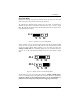
Card Setup Interrupt Modes Headers J1A through J4A select the interrupt modes for each port. Each port must be set in the correct mode to insure proper operation. ‘N’ indicates the (N)ormal, single interrupt per port mode. ‘S’ Indicates the (S)hared interrupt mode, which allows more than one port to access a single IRQ. ‘M’ indicates the inclusion of a 1K ohm pull-down resistor required on one port when sharing interrupts.
Card Setup Clock Modes The VERSA COMM+4/EX employs a unique clocking option that allows the end user to select from divide by 4, divide by 2 and divide by 1 clocking modes. This mode is selected at J5. To select the Baud rates commonly associated with COM: ports (i.e. 2400, 4800, 9600, 19.2, … 115.2K Bps) place the jumper in the divide by 4 mode (silk-screen DIV4). DIV1 DIV2 DIV4 Figure 7 - Clocking Mode ‘Divide By 4’ To double these rates up to a maximum rate for 230.
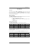
Card Setup Baud Rates and Divisors for the ‘Div1’ mode The following table shows some common data rates and the rates you should choose to match them if using the adapter in the ‘Div1’ mode. For this Data Rate 1200 bps 2400 bps 4800 bps 9600 bps 19.2K bps 57.6 K bps 115.2 K bps 230.4K bps 460.8K bps Choose this Data Rate 300 bps 600 bps 1200 bps 2400 bps 4800 bps 9600 bps 19.2K bps 57.6 K bps 115.
Card Setup Baud Rates and Divisors for the ‘Div2’ mode The following table shows some common data rates and the rates you should choose to match them if using the adapter in the ‘Div2’ mode. For this Data Rate 1200 bps 2400 bps 4800 bps 9600 bps 19.2K bps 38.4K bps 57.6 K bps 115.2 K bps 230.4 K bps Choose this Data Rate 600 bps 1200 bps 2400bps 4800 bps 9600 bps 19.2K bps 38.4K bps 57.6 K bps 115.
Installation Installation Operating System Installation For Windows Users Start by choosing Install Software at the beginning of the CD. Choose Asynchronous COM: Port Software, SeaCOM. Other Operating Systems Refer to the appropriate section of the Serial Utilities Software. System Installation The VERSA COMM+4/EX can be installed in any of the PC ISA expansion slots. The VERSA COMM+4/EX contains several jumper straps for each port that must be set for proper operation. 1. 2. 3. 4. 5. 6. 7. 8.
Technical Description Technical Description The VERSA COMM+4/EX utilizes the 16C554 UART. This chip features programmable baud rate, data format, interrupt control and a 16-byte input and output FIFO, and is functionally 4 16C550 UARTs. A full array of advanced UARTs is also available for this card. Contact Sealevel Systems, Inc. for more information.
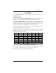
Technical Description Connector Pin Assignments DB-25 Male (RS-232 DTE) Signal GND TD RTS DTR RD CTS DSR DCD RI Name Ground Transmit Data Request To Send Data Terminal Ready Receive Data Clear To Send Data Set Ready Data Carrier Detect Ring Indicator Pin # 7 2 4 20 3 5 6 8 22 Mode Output Output Output Input Input Input Input Input DB-9 Male (EIA-574 DTE) Signal GND TD RTS DTR RD CTS DSR DCD RI Name Ground Transmit Data Request To Send Data Terminal Ready Receive Data Clear To Send Data Set Ready Data
Technical Description DB-37 Male Port # GND TD RTS DTR RD CTS DSR DCD RI 1 33 35 17 34 36 16 18 37 15 2 14 12 30 13 11 31 29 10 32 3 24 26 8 25 27 7 9 28 6 4 5 3 21 4 2 22 20 1 23 Technical Note: Please terminate any control signals that are not going to be used. The most common way to do this is connect RTS to CTS and RI. Also, connect DCD to DTR and DSR. Terminating these pins, if not used, will help insure you get the best performance from your adapter.
Specifications Specifications Environmental Specifications Specification Temperature Range Humidity Range Operating 0º to 50º C (32º to 122º F) 10 to 90% R.H. Non-Condensing Storage -20º to 70º C (-4º to 158º F) 10 to 90% R.H. Non-Condensing Manufacturing • All Sealevel Systems Printed Circuit boards are built to U.L. 94V0 rating and are 100% electrically tested. These printed circuit boards are solder mask over bare copper or solder mask over tin nickel.
Appendix A - Troubleshooting Appendix A - Troubleshooting Serial Utility test software is supplied with the Sealevel Systems adapter and will be used in the troubleshooting procedures. By using this software and following these simple steps, most common problems can be eliminated without the need to call Technical Support. 1. Identify all I/O adapters currently installed in your system. This includes your on-board serial ports, controller cards, sound cards etc.
Appendix A - Troubleshooting 8. The following are known I/O conflicts: • • • • • • The 278 and 378 settings may conflict with your printer I/O adapter. 3B0 cannot be used if a Monochrome adapter is installed.
Appendix B - How To Get Assistance Appendix B - How To Get Assistance Please refer to Troubleshooting Guide prior to calling Technical Support. 1. Begin by reading through the Trouble Shooting Guide in Appendix A. If assistance is still needed please see below. 2. When calling for technical assistance, please have your user manual and current adapter settings. If possible, please have the adapter installed in a computer ready to run diagnostics. 3.
Appendix C - Electrical Interface Appendix C - Electrical Interface RS-232 Quite possibly the most widely used communication standard is RS-232. This implementation has been defined and revised several times and is often referred to as RS-232-C/D/E or EIA/TIA-232-C/D/E. It is defined as “Interface between Data Terminal Equipment and Data Circuit- Terminating Equipment Employing Serial Binary Data Interchange”. The mechanical implementation of RS-232 is on a 25-pin D sub connector.
Appendix D - Asynchronous Communications Appendix D - Asynchronous Communications Serial data communications implies that individual bits of a character are transmitted consecutively to a receiver that assembles the bits back into a character. Data rate, error checking, handshaking, and character framing (start/stop bits) are pre-defined and must correspond at both the transmitting and receiving ends.
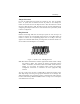
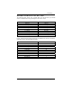
Appendix E - Silk-Screen Appendix E - Silk-Screen 3.1" 5.2" 3.
Appendix F - Schematic Appendix F - Schematic Sealevel Systems VERSA COMM+4/EX Page 20
P1 P1 P1 P1 P1 P1 P2 P2 P2 P2 B25 B24 B23 B22 B21 B4 D3 D4 D5 D6 1 1 1 1 1 1 1 1 1 1 1 SHEET SHEET SHEET SHEET SHEET SHEET SHEET SHEET SHEET SHEET SHEET 50 48 46 44 42 8 6 8 10 12 IRQ3 IRQ4 IRQ5 IRQ6 IRQ7 IRQ9 IRQ10 IRQ11 IRQ12 IRQ15 BRESET BIOW BIOR BA0 BA1 BA2 CS1/ CS2/ CS3/ CS4/ CLK BD0 BD1 BD2 BD3 BD4 BD5 BD6 BD7 J1B 1 3 5 7 9 11 13 15 17 19 J4B 1 3 5 7 9 11 13 15 17 19 J3B 1 3 5 7 9 11 13 15 17 19 J2B 1 3 5 7 9 11 13 15 17 19 2 4 6 8 10 12 14 16 18 20 2 4 6 8 10 12 14 16 18 20 2 4 6 8
Appendix G - Compliance Notices Appendix G - Compliance Notices Federal Communications Commission Statement FCC - This equipment has been tested and found to comply with the limits for Class A digital device, pursuant to Part 15 of the FCC Rules. These limits are designed to provide reasonable protection against harmful interference when the equipment is operated in a commercial environment.
Warranty Warranty Sealevel Systems, Inc. provides a limited lifetime warranty. Should this product fail to be in good working order at any time during this period, Sealevel Systems will, at it’s option, replace or repair it at no additional charge except as set forth in the following terms. This warranty does not apply to products damaged by misuse, modifications, accident or disaster.