Ultra-SIO Users Manual Part # 3089 and 3189 Sealevel Systems, Inc. PO Box 830 Liberty, SC 29657 USA Telephone: 864.843.4343 Fax: 864.843.3067 www.sealevel.
Contents INTRODUCTION ........................................................................................................................ 1 OVERVIEW .............................................................................................................................................. 1 WHAT’S INCLUDED ................................................................................................................................. 1 FACTORY DEFAULT SETTINGS ........................................
Figures Figure 1 - Address Selection Table.................................................................................................................... 2 Figure 2 - Header E11 and E12, IRQ Selection................................................................................................ 3 Figure 3 - Header E5 & E6, Normal IRQ Mode .............................................................................................. 3 Figure 4 - Header E5 & E6, Shared IRQ Mode .........................
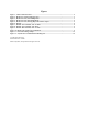
Introduction Introduction Overview The Sealevel Systems Ultra-SIO provides the PC with two additional ground isolated RS-422/485 (P/N 3189) or two non-isolated RS-422/485 (P/N 3089) serial ports for terminals, modems, printers, etc. Isolation is important in installations where the equipment being connected to the PC is either far from the PC, or on a different power transformer circuit.
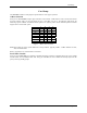
Card Setup Card Setup The Ultra-SIO contains several jumper straps that must be set for proper operation. Address Selection Each port on the Ultra-SIO occupies eight consecutive I/O locations. A DIP-switch is used to set the base address for these locations. SW1 sets the I/O address for port 1 and SW2 sets port 2. The following table shows the addressing options available. If different address options are required, please contact Sealevel Systems Technical Support about a custom PAL option.
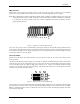
Card Setup IRQ Selection Headers E11 and E12 select the interrupt request for each serial port. If COM1: is selected, the corresponding jumper must be on the IRQ4 setting. If COM2: is selected, the corresponding jumper must be on IRQ3. 15 14 12 11 10 7 6 5 4 3 2/9 Note: Most communications software applications default COM3: to IRQ4 and COM4: to IRQ3. This requires the sharing of interrupts between COM1: and COM3:, and between COM2: and COM4:.
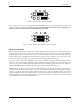
Card Setup N S M 1 2 E5 E6 Figure 4 - Header E5 & E6, Shared IRQ Mode Set the jumper to ‘S’ if you are using more than one Ultra-SIO in a bus or to completely remove the pull-down resistor for hardware compatibility. Setting the adapter in this configuration when it is not accompanied by a pull-down resistor will prevent the ports from triggering an interrupt.
Card Setup Headers E3 (Port 1) and E9 (Port 2) are used to control the RS-485 enable/disable functions for the receiver circuit and determine the state of the RS-422/485 driver. The RS-485 ‘Echo’ is the result of connecting the receiver inputs to the transmitter outputs. Every time a character is transmitted; it is also received. This can be beneficial if the software can handle echoing (i.e. using received characters to throttle the transmitter) or it can confuse the system if the software does not.
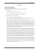
Card Setup RTS Auto E8 & E10 E3 & E9 Figure 8 - RS-485 ‘Auto’ Enabled, with ‘Echo’ RTS Auto E8 & E10 E3 & E9 Figure 9 - RS-485 ‘RTS’ Enabled, with ‘No Echo’ Line Termination Typically, each end of the RS-485 bus must have line terminating resistors (RS-422 terminates at the receive end only). A 120 ohm resistor is across each RS-530/422/485 input in addition to a 1K ohm pull-up/pull-down combination that bias the receiver inputs.
Installation Installation Operating System Installation Windows 95/98/ME/NT/2000/XP Do not install the adapter in the machine until the software has been fully installed. 1. Start Windows. 2. Insert the Sealevel Systems CD in to your CD drive. 3. If ‘Auto-Start’ is enabled for this drive the software will automatically launch. 4. Otherwise, point your browser to the ‘Index.htm’ on the root of the CD 5. The next step is to select ‘Install Software’. 6.
Installation Linux Refer to D:\software\seacom\Other\Linux\Linux.serial.readme (where D: = your CDROM driver letter) found on the Sealevel Systems CD. This file contains valuable information on installing your adapter in the various Linux releases. Also in this sub-directory is the Linux SerialHOWTO. This series of files explains typical Linux serial implementations, as well as informing the user to Linux syntax and preferred practices. QNX Refer to D:\software\seacom\Other\QNX6\Install.
Technical Description Technical Description The Sealevel Systems Ultra-SIO provides the PC with two additional ground isolated RS-422/485 (P/N 3189) or two non-isolated RS-422/485 (P/N 3089) serial ports for terminals, modems, printers, etc. Isolation is important in installations where the equipment being connected to the PC is either far from the PC, or on a different power transformer circuit.
Specifications Specifications Environmental Specifications Specification Temperature Range Humidity Range Operating 0º to 70º C (32º to 158º F) 10 to 90% R.H. Non-Condensing Storage -50º to 105º C (-58º to 221º F) 10 to 90% R.H. Non-Condensing Manufacturing All Sealevel Systems Printed Circuit boards are built to UL 94V0 rating and are 100% electrically tested. These printed circuit boards are solder mask over bare copper or solder mask over tin nickel.
Appendix A - Troubleshooting Appendix A - Troubleshooting Sealevel Software is supplied with the Sealevel Systems adapter and may be used in the troubleshooting procedures. Using this software and following these simple steps can eliminate most common problems without the need to call Technical Support. 1. Identify all I/O adapters currently installed in your system. This includes your on-board serial ports, controller cards, sound cards etc.
Appendix B - How To Get Assistance Appendix B - How To Get Assistance Please refer to Troubleshooting Guide prior to calling Technical Support. 1. Begin by reading through the Trouble Shooting Guide in Appendix A. If assistance is still needed please see below. 2. When calling for technical assistance, please have your user manual and current adapter settings. If possible, please have the adapter installed in a computer ready to run diagnostics. 3.
Appendix C – Electrical Interface Appendix C - Electrical Interface RS-422 The RS-422 specification defines the electrical characteristics of balanced voltage digital interface circuits. RS-422 is a differential interface that defines voltage levels and driver/receiver electrical specifications. On a differential interface, logic levels are defined by the difference in voltage between a pair of outputs or inputs.
Appendix D - Ground Loop Phenomenon Appendix D - Ground Loop Phenomenon What is Ground Loop? Ground loop Phenomenon occurs when two (or more) pieces of equipment are connected together with a common ground and a different ground potential exists at each location. This current can cause the connected equipment to experience noise that in turn causes data transmission errors. In the extreme this ground current can cause equipment malfunction or even destruction.
Appendix E - Asynchronous Communications Appendix E - Asynchronous Communications Serial data communications implies that individual bits of a character are transmitted consecutively to a receiver that assembles the bits back into a character. Data rate, error checking, handshaking, and character framing (start/stop bits) are pre-defined and must correspond at both the transmitting and receiving ends.
Appendix F - Silk-Screen Appendix F - Silk-Screen 5.2" 4.
Appendix G - Compliance Notices Appendix G - Compliance Notices Federal Communications Commission Statement FCC - This equipment has been tested and found to comply with the limits for Class A digital device, pursuant to Part 15 of the FCC Rules. These limits are designed to provide reasonable protection against harmful interference when the equipment is operated in a commercial environment.
Warranty Warranty Sealevel's commitment to providing the best I/O solutions is reflected in the Lifetime Warranty that is standard on all Sealevel manufactured products. We are able to offer this warranty due to our control of manufacturing quality and the historically high reliability of our products in the field. Sealevel products are designed and manufactured at its Liberty, South Carolina facility, allowing direct control over product development, production, burn-in and testing. Sealevel Systems, Inc.