ISO-16 User Manual Part Number 3094 www.sealevel.com PO Box 830 Liberty, SC 29657 864.843.
Table of Contents INTRODUCTION......................................................................................................................... 1 OTHER SEALEVEL ISA DIGITAL I/O PRODUCTS .......................................................................... 1 BEFORE YOU GET STARTED................................................................................................. 2 WHAT’S INCLUDED .......................................................................................................
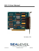
Introduction The ISO-16 provides 16 optically isolated inputs (rated for 3-13V) to allow monitoring of off board switch closures, relays or for any other general purpose monitoring needs. The ISO-16 is PCI 2.1 bus compliant. The ISO-16 is designed to be used with a variety of Operating Systems including Windows 98/NT/ME/2000/XP, Linux and DOS.
Before You Get Started What’s Included The ISO-16 is shipped with the following items. If any of these items is missing or damaged please contact Sealevel for replacement. ISO-16 Adapter Sealevel SeaI/O Software CD Optional Items Depending upon your application, you are likely to find one or more of the following items useful for interfacing the ISO-16 to real-world signals. All items can be purchased from our website (http://www.sealevel.com) or by calling (864) 8434343.
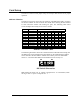
Card Setup The ISO-16 contains several jumper straps for each port that must be set for proper operation. Address Selection The ISO-16 occupies 4 consecutive I/O locations. The DIP-switch (SW1) is used to set the base address for these locations. Be careful when selecting the base address as some selections conflict with existing PC ports. The following table shows several examples that usually do not cause a conflict.
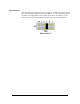
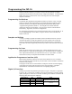
IRQ Header E1 Interrupts can be generated by Port A, bit 0 going low if enabled at jumper location (E1). Interrupt request signals 2/9 through 7 (IRQ 2/9 - 7) can be selected by placing the jumper in the appropriate position. Other inputs can be ‘wire OR ed.’ to also generate interrupts if desired. Please consult the factory for more information. IRQ Header E1 © Sealevel Systems, Inc.
Software Installation Windows 98/ME/NT/2000/XP Installation Do not install the Adapter in the machine until the software has been fully installed. 1. Start Windows. 2. Insert the Sealevel Systems CD in to your CD drive. 3. If ‘Auto-Start’ is enabled for this drive the software will automatically launch. Otherwise, point your browser to the ‘Index.htm’ on the root directory of the CD 4. Select ‘Install Software’. 5. Select the Part Number for your adapter from the listing. 6.
Linux Installation Note: You MUST have "root" privileges to install the software and drivers. 1. Login as "root". 2. Mount the CDROM by typing: mount -t iso4860 /dev/hdc /cdrom Note Your cdrom may not be /dev/hdc it could be /dev/hda, /dev/hdb, /dev/hdd, or if you have a SCSI drive /dev/sda, /dev/sdb, /dev/sdc, etc. You may mount the CDROM to any location, the /cdrom is just a common example. 3. Next change to the directory where you mounted the CDROM: Ex.
Physical Installation The adapter can be installed in any 5V PCI expansion slot. Do not install the Adapter in the machine until the software has been fully installed. 1. Turn off PC power. Disconnect the power cord. 2. Remove the PC case cover. 3. Locate an available 5V PCI slot and remove the blank metal slot cover. 4. Gently insert the PCI adapter into the slot. Make sure that the adapter is seated properly. 5. Replace the screw you removed for the blank and use it to secure the adapter into the slot.
Programming the ISO-16 Sealevel’s SeaI/O software is provided to assist in the development of reliable applications for the Sealevel Systems family of digital I/O adapters. Included on the SeaI/O CD are driver functions for use in accessing the I/O as well as helpful samples and utilities. Programming for Windows The SeaI/O API (Application Programmer Interface) provides a variety of useful high-level function calls implemented in a Windows dynamic link library (DLL).
Input Ports Ports A and B are 8 bit input ports connected to optically isolated input sensors. Each sensor can be used to interface a voltage input and then sense whether the voltage is on or off. Each sensor is isolated with respect to a common ground from every other sensor and also isolated with respect to the host PC ground.
Sensor Input Ports Pin Assignments (P1) Port A Bit 0 1 2 3 4 5 6 7 Ground + 12 Volts + 5 Volts P1 18,37 17,36 16,35 15,34 14,33 13,32 12,31 11,30 2,20,21 19 1 Port B Bit 0 1 2 3 4 5 6 7 P1 10,29 9, 28 8,27 7,26 6,25 5,24 4,23 3,22 Pin Assignments Port A Bit A0 A1 A2 A3 A4 A5 A6 A7 B0 B1 B2 B3 B4 B5 B6 B7 Ground + 12 Volts + 5 Volts P1 18,37 17,36 16,35 15,34 14,33 13,32 12,31 11,30 10,29 9, 28 8,27 7,26 6,25 5,24 4,23 3,22 2,20,21 19 1 Note: For ease in wiring, the card’s DB37 connector can be interfa
Relative Addressing vs. Absolute Addressing The SeaIO API makes a distinction between “absolute” and “relative” addressing modes. In absolute addressing mode, the Port argument to the API function acts as a simple byte offset from the base I/O address of the device. For instance, Port #0 refers to the I/O address base + 0; Port #1 refers to the I/O address base + 1. Relative addressing mode, on the other hand, refers to input and output ports in a logical fashion.
Interrupt Control When enabled, interrupts are generated on Port A bit D0. IRQEN IRC0 IRC1 Interrupt enable 1 = enabled 0 = disabled ( 0 on power up ) Interrupt mode select, see table below Interrupt mode select, see table below Interrupt Mode Select Table Interrupt source is Base+0 bit D0. When selecting the Interrupt Type, always disable interrupts prior to changing or setting states. This will help prevent inadvertent or unexpected interrupts from occurring.
Electrical Characteristics Features Selectable I/O port addressing from 100H – 3FFH 2 eight bit input ports Multiple adapters can reside in same computer All address, data and control signals are TTL compatible Specifications Input Ports Turn On Current: Isolator Diode Drop: Resistor Power Max: Maximum Input Range: 3mA 1.1 VDC .
Example Circuits Input Circuit © Sealevel Systems, Inc.
Appendix A - Troubleshooting Following these simple steps can eliminate most common problems. 1. Install software first. After installing the software then proceed to adding the hardware. This places the required installation files in the correct locations. 2. Read this manual thoroughly before attempting to install the adapter in your system. 3. Use Device Manager under Windows to verify proper installation. 4.
Appendix B - How To Get Assistance Begin by reading through the Trouble Shooting Guide in Appendix A. If assistance is still needed please see below. When calling for technical assistance, please have your user manual and current adapter settings. If possible, please have the adapter installed in a computer ready to run diagnostics. Sealevel Systems provides an FAQ section on its web site. Please refer to this to answer many common questions. This section can be found at http://www.sealevel.com/faq.
Appendix C – Silk Screen – 3094 PCB 4.2" 4.9" 3.9" © Sealevel Systems, Inc.
Appendix D - Compliance Notices Federal Communications Commission Statement FCC - This equipment has been tested and found to comply with the limits for Class A digital device, pursuant to Part 15 of the FCC Rules. These limits are designed to provide reasonable protection against harmful interference when the equipment is operated in a commercial environment.
Warranty Sealevel's commitment to providing the best I/O solutions is reflected in the Lifetime Warranty that is standard on all Sealevel manufactured products. We are able to offer this warranty due to our control of manufacturing quality and the historically high reliability of our products in the field. Sealevel products are designed and manufactured at its Liberty, South Carolina facility, allowing direct control over product development, production, burn-in and testing. Sealevel Systems, Inc.