TM SeaLINK+8/USB Part # 280X Sealevel Systems, Inc P.O. Box 830 Liberty, SC 29657 USA Phone: (864) 843-4343 FAX: (864) 843-3067 www.sealevel.
Contents INTRODUCTION ........................................................................ 1 INSTALLATION INSTRUCTIONS ................................................ 2 PHYSICAL INSTALLATION ...............................................................3 CONFIGURATION ..................................................................... 5 FACTORY CONFIGURATION .............................................................5 ELECTRICAL INTERFACE SELECTION ..............................................
Introduction Introduction Overview The Sealevel Systems SeaLINK+8 family of products equips the PC with 8 USB to Asynchronous serial ports. Three different model numbers are available that offer a variety of port options. Model 2801 equips the PC with 8 additional RS-232 ports that support a full RS-232 interface and data rates up to 460.8K baud. Model 2802 equips the PC with 8 RS-422/485 ports that support data rates up to 921.6K baud and provide selectable line termination and biasing.
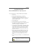
Installation Installation Instructions Windows 98/ME/2000/XP/Vista™ Operating Systems Do not connect the device to a USB port until the software is installed. 1. Start Windows. 2. Insert the Sealevel Software CD in to your CD drive. 3. If ‘Auto-Start’ is enabled the installation window will automatically appear. Otherwise, navigate to the root directory of your CD drive and double-click the ‘autorun.exe’ application to launch the installation window. 4. Select ‘Install Software’. 5.
Installation Physical Installation The screen captures below are taken from a Windows 98 installation. Your particular operating system may differ slightly from what is shown based on your version of Windows. The SeaLINK+8 can be connected to any upstream type “A” port, either at the PC host or an upstream hub. The SeaLINK+8 is hot pluggable, meaning there is no need to power down your computer prior to installation. Connect the SeaLINK+8 to an upstream host or hub.
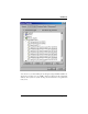
Installation You can access your new COM: ports by using the assigned COM: identifiers as shown above. In this case, it is COM’s 12 thru 19. However, this assignment will vary from system to system. At this point, the hardware is recognized and ready to use.
Configuration Configuration Factory configuration Each device ships from Sealevel Systems with the following configuration. Model 2801 – SeaLINK+8/232 USB to RS-232 Converter Contains no user configurable components. Model 2802 – SeaLINK+8/485 USB to RS-422/485 Converter RS-422 4-wire full duplex mode selected. Transmitter always enabled.
Configuration Below is a figure of dipswitches SW1, SW2, SW3, and SW4. Each switch has a total of twelve positions and serves to configure two ports. Six positions are used for each port. The default mode of RS-422 4-wire full duplex is shown.
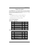
Configuration Interface Biasing Configuration The last four positions for each port are used to select the line termination and bias settings. Refer to the chart below for specific switch settings of the three supported electrical interface modes. Note that this chart appears in the silk screen on the board as well. PD = 1Kohm pull-down resistor connected to RXRS-232 mode = always OFF RS-422 mode = always ON RS-485 mode = ON if not provided by another device on the bus PU = 5.
Specifications Technical Description The SeaLINK+8 utilizes eight USB UARTs. These chips feature programmable baud rate, data format, 128 byte Dual Port TX Buffer, and 384 byte Dual Port RX Buffer. The RS-232/422/485 transceiver supports data rates up to 921.6K baud for RS-422/485 and 460.8K baud for RS-232. Features • Hot pluggable device that does not require opening the case • No system resources are required (i.e.
Specifications Specifications Environmental Specifications Specification Temperature Range Humidity Range Operating 0º to 50º C (32º to 122º F) 10 to 90% R.H. Non-Condensing Storage -20º to 70º C (-4º to 158º F) 10 to 90% R.H. Non-Condensing Manufacturing • All Sealevel Systems Printed Circuit boards are built to UL 94V0 rating and are 100% electrically tested. These printed circuit boards are solder mask over bare copper or solder mask over tin nickel.
Appendix A – Troubleshooting Appendix A - Troubleshooting Serial Utility test software is supplied with the Sealevel Systems adapter and will be used in the troubleshooting procedures. Using this software and following these simple steps, most common problems can be eliminated without the need to call Technical Support. 1. If your adapter isn’t working, first check to make sure that USB support is enabled in the System BIOS and it is functioning properly in the operating system.
Appendix B – How To Get Assistance Appendix B - How To Get Assistance Please refer to Appendix A - Troubleshooting prior to calling Technical Support. 1. Read this manual thoroughly before attempting to install the adapter in your system. 2. When calling for technical assistance, please have your user manual and current adapter settings. If possible, please have the adapter installed in a computer ready to run diagnostics. 3. Sealevel Systems maintains a web site on the Internet. The address is www.
Appendix C - Electrical Interface Appendix C - Electrical Interface RS-232 Quite possibly the most widely used communication standard is RS-232. This implementation has been defined and revised several times and is often referred to as RS-232 or EIA/TIA-232. The IBM PC computer defined the RS-232 port on a 9 pin D sub connector and subsequently the EIA/TIA approved this implementation as the EIA/TIA-574 standard.
Appendix C - Electrical Interface RS-485 RS-485 is backwardly compatible with RS-422; however, it is optimized for party line or multi-drop applications. The output of the RS-422/485 driver is capable of being Active (enabled) or Tri-State (disabled). This capability allows multiple ports to be connected in a multi-drop bus and selectively polled. RS-485 allows cable lengths up to 4000 feet and data rates up to 10 Megabits per second. The signal levels for RS-485 are the same as those defined by RS-422.
Appendix D - Asynchronous Communications Appendix D - Asynchronous Communications Serial data communications implies that individual bits of a character are transmitted consecutively to a receiver that assembles the bits back into a character. Data rate, error checking, handshaking, and character framing (start/stop bits) are pre-defined and must correspond at both the transmitting and receiving ends.
Appendix E - Compliance Notices Appendix E - Compliance Notices Federal Communications Commission Statement FCC - This equipment has been tested and found to comply with the limits for Class A digital device, pursuant to Part 15 of the FCC Rules. These limits are designed to provide reasonable protection against harmful interference when the equipment is operated in a commercial environment.
Warranty Warranty Sealevel Systems, Inc. provides a lifetime warranty for this product. Should this product fail to be in good working order at any time during this period, Sealevel Systems will, at it's option, replace or repair it at no additional charge except as set forth in the following terms. This warranty does not apply to products damaged by misuse, modifications, accident or disaster.