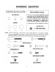
NOTE: Please read all instructions carefully before using this product Safety Notice POWERHOUSE Bi-Level Dumbbell Rack Hardware Identifier DBR 90 Assembly Instruction Parts List Warranty Ordering Parts Model DBR 90 Retain This Manual for Reference 06-25-01 IMPEX FITNESS PRODUCTS OWNER'S MANUAL 14777 DON JULIAN RD., CITY OF INDUSTRY, CA 91746 Tel: (800) 999-8899 Fax: (626) 961-9966 www.impex-fitness.com info@impex-fitness.
TABLE OF CONTENTS BEFORE YOU BEGIN...................................................................................... IMPORTANT SAFETY NOTICES..................................................................... HARDWARE IDENTIFIER.....…....................................................................... ASSEMBLY INSTRUCTIONS........................................................................... EXPLODED DIAGRAM.........................................................................……….
IMPORTANT SAFETY NOTICE PRECAUTIONS This exercise machine is built for optimum safety. However, certain precautions apply whenever you operate a piece of exercise equipment. Be sure to read the entire manual before you assemble or operate your machine. In particular, note the following safety precautions: 1. Keep children and pets away from the machine at all times. DO NOT leave children unattended in the same room with the machine. 2. Only one person at a time should use the machine. 3.
3
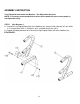
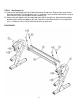
ASSEMBLY INSTRUCTION Tools Required to Assemble the Machine: Two Adjustable Wrenches NOTE: It is strongly recommended this machine be assembled by two or more people to avoid possible injury. STEP 1 (See Diagram 1) A.) Connect the Left Upright Beam (#3) to the Stabilizer (#1). Secure it with a Bracket (#7), four M10 x 3 ¼” Carriage Bolts (#10), ∅ ¾” Washers (#12), and M10 Aircraft Nuts (#13). B.) Repeat the above procedure A to Connect the Right Upright Beam (#2) to the Stabilizer (#1).
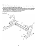
STEP 2 (See Diagram 2) A.) Connect the two Uprights with one Fixed Rack (#4) on the top level. Align the holes then Secure them with two M10 x 2 ¾” Carriage Bolts (#11), ∅ ¾” Washers (#12), and M10 Aircraft Nuts (#13) on each end of the Rack. Do not tighten the nuts and bolts yet. B.) Connect the two Uprights with one Adjustable Rack (#5) on the top level. Align the Rack width by positioning the smallest dumbbell on the rack.
STEP 3 (See Diagram 3) A.) Connect the two Uprights with one Fixed Rack (#4) on the lower level. Align the holes then Secure them with two M10 x 2 ¾” Carriage Bolts (#11), ∅ ¾” Washers (#12), and M10 Aircraft Nuts (#13) on each end of the Rack. Do not tighten the nuts and bolts yet. B.) Connect the two Uprights with one Adjustable Rack (#5) on the lower level. Align the Rack width by positioning the smallest dumbbell on the rack.
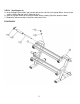
STEP 4 (See Diagram 4) A.) Insert a Weight Plate Holders (#6) into the hole on the side of the Left Upright Beam. Secure it with a M10 x ¾” Allen Bolt (#9) and ∅ ¾” Washer (#12). B.) Slide an Olympic Sleeve (#16) onto the Holder. Attach a Spring Clip (#14) onto the Holder. C.) Repeat the above two steps to install the other three Posts.
8
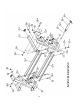
Parts list KEY NO.
IMPEX INC. LIMITED WARRANTY IMPEX Inc. ("IMPEX") warrants this product to be free from defects in workmanship and material, under normal use and service conditions, for a period of two years on the Frame from the date of purchase. This warranty extends only to the original purchaser. IMPEX's obligation under this Warranty is limited to replacing or repairing, at IMPEX's option. All returns must be pre-authorized by IMPEX.