
Installation Guide

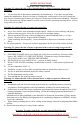


Wall Mount Installation Detail:
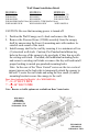
4. Bring conduit down and feed through 7/8”
hole on top of the canopy, at least 18” to
24” long. Be sure that the conduit hangs
4” past the bottom of the canopy.
5. Remove junction box cover from the
C2000. BP1 does not have C2000, junction
box is on the inside top of unit. (Be sure to
comply with all local electrical and safety
codes) Remove Black Tape that holds the
Damper Blades in closed position. Attach
special length of vent pipe to the vent
opening on the C2000 (using Automatic
Vent Collar) to extend through opening in
the top of the canopy.
6. Position the C2000 (with vent pipe in the
Collar) into the canopy, with support
bolts through the holes in the top of the
C2000. Secure washers and nuts on all
Weld Studs, tighten securely.
7. Hook up electrical wires and secure
electrical cover.
8. Install lights and replace filters. For
Baffle Filters, install grease tray towards
the back of liner. Take one baffle, slide
between steel strips towards the front of
the liner and push back into grease tray
grooves, then slide to one side. Insert
second baffle the same way and slide to
opposite side. (Grease holes, on bottom
of baffle must be inserted into grease
tray) Take Center Panel and slide in
towards the front of the liner and push
back into grease tray.
*Attaching Duct Cover: Remove tape on brackets and
attach duct cover.
TWIN UNITS ONLY
Transitioning two pipes into one is NOT
recommended. CFMs are reduced by 25% and the Per-
formance warranty will be void.
18"
(+/- 1/16")
Electrical
Back
Front
24"
9-1/8"
1
-
1
/
2
"
1
-
3
/
4
"
8-1/2"
7/8"
1-1/2"
4-1/2"
6-3/4"
11- 3/4 "
4"
2
9
-
1
3
/
1
6
"
"
o
r
3
5
-
1
3
/
1
6
"
i
n
W
H1
9
0
0
P
S
1
2
9
-
1
3
/
1
6
"
,
3
5
-
1
3
/
1
6
"
,
4
1
-
1
3
/
1
6
"
o
r
4
7
-
1
3
/
1
6
"
i
n
W
H
1
9
0
0
P
S
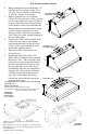
WH1900PS, WH1900PS1
WH1900PSB, WH1900PS1B
WHP1900PS1-TW
3
5
-
1
3
/
1
6
"
,
4
1
-
1
3
/
1
6
"
,
4
7
-
1
3
/
1
6
"
,
5
3
-
1
3
/
1
6
"
o
r
5
9
-
1
3
/
1
6
"
Back
Front
18"
(+/- 1/16")
24"
9-1/8"
1
-
1
/
2
"
1
-
3
/
4
"
8-1/2"
7/8"
1
-
1
/
2
"
4
-
1
/
2
"
6
"
6-3/4"
11-3/4"
4"
4
-
1
/
2
"
6
"
C
e
n
t
e
r
L
i
n
e
3
6
"
o
n
l
y
=
4
-
1
/
2
"
4
2
"
o
r
L
a
r
g
e
r
=
6
"
E
l
e
c
t
r
i
c
a
l
WH1900PS1-TW
WH1900PS1-TWB
4
7
-
1
3
/
1
6
"
,
5
3
-
1
3
/
1
6
"
o
r
5
9
-
1
3
/
1
6
"
12"
(+/- 1/16")
Electrical
24"
4"
2
4
"
,
3
0
"
&
3
6
"
11-3/ 4"
Stack Brackets are
1/4" in from edge.
6"
6"
5-3/4"
8-1/2"
1
-
1
/
2
"
8-1/2"
7/8"
WHP1900BP1*
WHP1900SD4**
WHP1900SD2-8
has 8” round duct
WHP1900PS
WHP1900PS1
P
S
1
—
3
0
”
,
3
6
”
&
4
2
”
P
S
—
3
6
”
,
4
2
”
&
4
8
”
**BP1 does not have C2000 Liner. Junction box is on the
inside top of unit.
BP1 Includes: 10-1/4”-3-1/2” rectangle to 7” round transition
with adapter piece. If you have rectangular piping, no need to
use transition piece.
**SD4 has single 7” Round Duct.