
IMO data sheet

Technical Specications
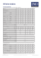
Data according to IEC 947-3, IEC 947-5-1, VDE 0660, EN 60947-3, EN 60947-5-1
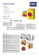
69 Series Isolators
Technical Datasheet
Errors and omissions excepted. Subject to change without notice. © 2021 IMO Precision Controls Ltd For more information visit www.imopc.com
Type ..69..20 ..69..25 ..69..32 ..69..40 ..69..63 ..69..80 ..69..100 ..69..125
Main Contacts
Rated thermal current I
th
open A 20 25 32 40 63 80 100 125
Rated thermal current I
th
enclosed A 20 25 32 40 63 80 100 110
Rated insulation voltage U
i
1)
V 690 690 690 690 690 690 1000
3)
1000
3)
Rated operational current I
e
AC21A A 20 25 32 40 63 80 100 125
Making capacity I
eff
3x380-440V A 160 190 220 300 370 440 725 850
Breaking capacity 3x220-240V A 160 180 200 250 330 380 580 680
3x380-440V A 160 180 200 250 330 380 580 680
3x660-690V A 80 110 140 170 190 220 330 420
Disconnection property performed up to V 690 690 690 690 690 690 1000 1000
Motor switch AC3 3x400V A 12 16 23 30 37 37 60 72
Motor switch AC3 3x220-240V kW 3 4 5.5 7.5 11 11 18.5 22
Direct switching of single motors 3x380-440V kW 5.5 7.5 11 15 18.5 18.5 30 37
3x660-690V kW 5.5 7.5 11 15 18.5 18.5 22 30
Main switch AC23 3x400V A 16 20 25 32 45 45 72 85
Motor switch AC23A 3x220-240V kW 4 5.5 7.5 9 15 15 22 30
Main switch AC23B 3x380-440V kW 7.5 10 12.5 16 22 22 37 45
Safety switch 3x660-690V kW 5.5 7.5 11 15 18.5 18.5 30 37
Rated conditional short-circuit current 400V kA
eff
10 10 10 10 10 10 10 5
Max. fuse size gL (gG) A 25 35 40 40 63 80 100 125
Mechanical life x10
3
200 200 200 200 100 100 100 100
Rated short-time withstand current (1 sec. current) A 250 300 400 500 600 850 1200 1500
Temperature Range open -40°C to +90°C
enclosed -40°C to +40°C
storage -50°C to +90°C
Power loss per pole AC21 = I
th
P/pole [W] PM, SH 0.322 0.503 0.824 1.288 2.739 4.416 5.330 8.328
LB, DM, PE 0.364 0.569 0.933 1.458 2.739 4.416 5.330 8.328
R/pole [mΩ] PM, SH 0.805 0.805 0.805 0.805 0.690 0.690 0.533 0.533
LB, DM, PE 0.911 0.911 0.911 0.911 0.690 0.690 0.533 0.533
Cable cross sections mm
2
0.5 - 10 1 - 25 4 - 50
solid or stranded AWG 20 - 8 (10) 16 - 3 (10) 10 - 00 (10)
exible mm
2
0.5 - 6 4 - 16 10 - 35
AWG 20 - 10 16 - 6 8 - 2
exible (+ multicore cable end) mm
2
0.5 - 6 0.75 - 16 6 - 35
AWG 20 - 10 16 - 6 8 - 2
Size of terminal screw M3.5 M5 M6
Tightening torque Nm 1.7 - 2.3 2.8 - 4 1.7 - 4.5
Auxiliary contacts
Rated insulation voltage Ui
1)
V 690
Rated thermal current I
th
, i
the
A 10
Switching capacity AC15 220-240V A 2.5
AC15 380-440V A 1.5
Rated conditional short-circuit current kA
eff
3
Max. short circuit protection gL (gG) A 10
Cable cross sections mm
2
0.75 - 2.5
Solid or stranded AWG 14 - 12
Flexible (+ multicore cable end) mm
2
0.75 - 2.5 (1.5)
AWG 18 - 14
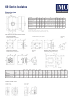
Rated voltage V 600 600 600 600 600 600 600 600
Ampere rating “General Use” A 20 25 32 40 63 80 100 125
DOL rating 3-phase 110 - 120V HP 1 1.5 2 2 3 5 10 15
220 - 240V HP 3 5 5 5 10 10 25 30
440 - 480V HP 7.5 10 10 10 20 20 50 60
550 - 600V HP 10 10 15 15 25 25 60 60
DOL rating 1-phase 110 - 120V HP 1 1 1 1 2 2 5 7.5
200 - 208V HP 1 2 2 2 3 3 10 10
220 - 240V HP 2 2 3 3 5 5 15 15
Fuse size (RK5) 5kA / 600V
Manual motor controller A 40 50 50 70 90 110 125 125
Motor disconnect A 40 50 50 50 70 70 125 125
Tightening torque Nm 1.7 - 2.3 2.8 - 4 1.7 - 4.5
lb.inch 11 - 20 24 - 35 15 - 40
1) Suitable for: earthed-neutral systems, overvoltage category I to III, pollution degree 3 (standard-industry): Uimp = 6kV. Data for other conditions on request
2) Fuse RK1 / 10kA / 600V
3) Uimp = 8kV
REF: 69 Series Isolators Datasheet 1121 v8
Data according to UL & cUL