EzUHF R/C Control System Overview & Operating Instructions Nov 2010, for Firmware v1.
Table of Contents Overview ....................................................................................................................................................... 3 Features/Specifications............................................................................................................................. 3 Security ..................................................................................................................................................... 4 Radio Licensing....
Overview The EzUHF R/C control system is a reliable R/C control uplink for FPV and UAV pilots who desire a robust control system for safe control at longer distances. It was designed with the FPV/UAV pilot in mind, the only such system with a dedicated head-tracker port, ensuring compatibility with a wide range of radios. An ‘Aux Ctrl’ port is available to connect to a ‘control board’, for in-flight UAV configuration without sacrificing valuable control channels.
Security The ImmersionRC team does not promote reckless long-range flight, where property and/or lives are put at risk. This R/C control system was brought to the market for use by responsible end-users, who are aware of, and comply with, local legislation regarding FPV/UAV flight. ImmersionRC accepts no responsibility for property damage, parts damage, model damage, or personal injury due to the misuse of the EzUHF, or any other ImmersionRC product.
As an example: Take the case of a R/C transmitter which uses a 2s LiPo pack. The EzUHF will emit slightly less power than specified (approx. 25dBm on 8v, vs. around 29dBm on 11.1v) when powered this way. In most cases this power difference is insignificant, for buzzing around the local flying field, this is a very reasonable power level.
See the advanced section, on how to bind multiple transmitters to a single receiver. Failsafe If, for any reason, the UHF link is broken, the receiver will wait for approximately 1 second for the link to be restored, and then will enter failsafe mode. The failsafe servo positions are programmed using the button on the transmitter. To set this up, two phases are recommended.
Transmitter Compatibility The PPM input circuit of the EzUHF Tx is designed to support a large range of transmitters, with PPM input voltages ranging from 3.3v, all the way to 9.6v or more. Most of the in-flight testing was performed using Futaba systems, which is used by the system's designers. This is therefore the preferred radio for use with the EzUHF link. Support for other radios will be added as further testing is done.
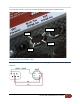
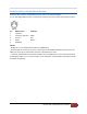
To remove any confusion, the pin-out is marked directly on a photo of the transmitter below: Not Used Gnd PPM In VBatt Futaba (square) to EzUHF cable: A Futaba to EzUHF cable is supplied with the EzUHF. The wiring diagram of this cable is shown below for reference.
Multiplex (DIN) to EzUHF (Mini-DIN) cable: Multiplex radios, with the standard DIN connector may be used with the EzUHF. A 5-pin, 180 degree DIN connector is required (even though more recent radios have a few extra pins). Pin 1 2 3 4 5 MPX Function +V battery +V battery, Switched Ground Out/In Disable HF EzUHF pin VBatt Gnd PPM In NOTES: - Bridge pins 3 + 5 to disable the HF module in all MPX radios. - Do not enable the trainer port as input, or the output will be disabled.
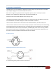
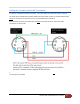
Cabling the TrackR2 to the EzUHF Transmitter: To cable the TrackR2 to the EzUHF transmitter a 4-pin Mini-DIN to 4-pin Mini-DIN cable is required. This cable will be available late November 2010 from ImmersionRC resellers. A standard S-Video cable cannot be used due to the necessity to cross over the PPM In/out connections. Note that both connectors are viewed from the back of the male connector, where the solder connections are to be made.
EzUHF Receivers The EzUHF receiver should be treated much like its 35/40/72MHz cousins. It requires 4.8->6v power to be applied through one of the servo connections, generally supplied from the ESC, or BEC in most models used for FPV.
EzUHF Receiver, 8 channel version, Connections Servo connectors on the 8 channel receiver have the pin-out shown below. Gnd +5/6v Signal Note that the binding button is not hidden under the padded label, it is located between the two stacked PCBs, and needs to be pressed using a non-conductive stylus, or similar. Powering the Rx when using high-powered servos It is very important to take care with powering the Rx, especially when high torque digital servos are used.
Receiver antenna configuration The 8 channel diversity receiver has, as its name might suggest, two antenna inputs. The receiver does expect antennas to be connected to both of these antenna connectors, unless configured otherwise. It is not advisable to leave the receiver configured in diversity mode, and connect just one antenna.
For DIY cables, the following Farnell parts may be used: 5-POS Molex ‘PicoBlade’ Housing Flying lead, 300mm 615109 1125274 The EzUHF Rx end of the cable uses a 5-pin Molex connector, as used for the GPS connection to the EzOSD PCB (the OSD end, not the GPS end).
On the EzOSD end, the wires should be connected as follows: Note: These can be simply spliced into the cable which connects the EzOSD to the current sensor. Red: +5v Black: Gnd Yellow: i2c SCL White: i2c SDA Note that when using the direct link between the EzOSD and the EzUHF, the RSSI calibration in the EzOSD is not required. This calibration feature applies only to the connection of an analog RSSI signal to the EzOSD.
significant amount of attenuation (something that should be very familiar to users of standard R/C radios). Turn 90 degrees to the model to avoid this. The antenna manufacturer Nagoya also sells a version of this (possibly made in the same factory), called the NA-771. This is generally a bit cheaper, and appears to perform as well. Active Robots 433MHz Straight http://www.active-robots.co.uk/433mhz-antenna-straight-p-544.
Even though the ImmersionRC receivers contain ceramic filters on the input stages, which attenuate higher-frequency RF emissions, it is highly recommended to separate the A/V Tx from the UHF Rx, and UHF antenna. Two configurations have been shown to work very well during hundreds of hours of flight testing. 1) A/V Tx out on a wingtip, with the EzUHF Rx antenna on the opposite wingtip 2) A/V Tx out on a wingtip, with the EzUHF Rx in the nose, and EzUHF antenna just in front of the vertical tail fin.
IMPORTANT: Known Sources of Interference There are several cameras which have been shown to emit broadband noise which can greatly limit the range of any UHF R/C system (FHSS or not). The use of these cameras should be avoided on any plane controlled by a UHF link. This list will be extended as more cameras are tested. KT&C ‘VSN505’ a.k.a KX550 Emits broadband noise in the ~310MHz to ~610MHz band Ground test range reduced to 30% of range without it.
Appendix A: Binding multiple transmitters to a single receiver This mode is useful in a couple of scenarios: 1) When redundancy is required, for safety reasons. One transmitter may be switched off, and another on, to recover the model. 2) To increase security during long range flights, or when a plane, once leaving line-of-sight for a first pilot, is passed to a second. This appendix will be completed once the feature is fully supported in the firmware.
Appendix B: Diagnostics Problem: Rx LED doesn’t light Check BEC voltage and polarity. Power the Rx via USB temporarily, if this causes the LED to light, and ‘beat’ when the Tx is powered on, then the BEC/Rx pack should be tested. Problem: No response from the Transmitter The transmitter should beep three times when the R/C transmitter is powered on.
Problem: RSSI values are good, but the link quality indicator is often below 100%. This is (in almost all cases) an interfering RF source located on the plane. Look for cameras which radiate unintentionally in the UHF band, or noisy switching regulators, especially those used to switch up from 5v to 12v to run a 12v camera.