
User manual


19
English
terminating plug (e. g. DLT-123 from IMG
STAGE LINE) to the DMX output jack.
The easiest way to terminate the DMX out-
put of the ODC-100/RGB is to separate an
extension cable ODP-34DMX and to connect
the resistor to the pins 2 and 3 of the plug.
Connect the plug with the resistor to the inline
jack of the cable DMX OUT. If no terminating
resistor is required, screw the protective cover
provided onto the inline jack of the cable.
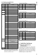
4.3.2 Setting the number of DMX channels
To operate the spotlight with a light controller,
the DMX start address (
☞
chapter 4.3.3) and the
number of DMX channels must be set. The num-
ber of DMX channels depends on the functions
required and may also depend on the number
of control channels that are available at the light
controller. Please refer to chapter 4.3.5 for more
information on the functions that are provided for
3-, 4-, 5- and 10-channel mode, and select the
number of DMX channels accordingly:
1)
Press the button MENU repeatedly until the
highest menu level has been reached (on the
very left in the menu structure on pages 78
and 79).
2)
Press the button UP or DOWN repeatedly until
the display indicates .
3) Press the button ENTER. The display now in-
dicates the current setting:
Setting Number of DMX channels
10
channels (
☞
chapter 4.3.5, fig. 8)
3
channels
1 = red, 2 = green, 3 = blue
4 channels
1 = dimmer, 2 = red, 3 = green, 4 = blue
5
channels
1 = dimmer, 2 = red, 3 = green,
4 = blue, 5 = stroboscope
3
channels
1 = colour, 2 = saturation,
3 = brightness
Fig. 5 Number of DMX channels
4)
Use the button UP or DOWN to select the
setting desired.
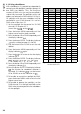
4.3.3 Setting the DMX start address
For separate control of all DMX units connected
to the light controller, each unit must have its
own start address. If the first DMX channel of the
spotlight is to be controlled by the light controller
via DMX address 17, for example, set the start
address on the spotlight to 17. All other DMX
channels of the spotlight will be automatically
assigned to the following addresses. The follow-
ing table is an example with the start address 17:
Number of
DMX channels
DMX
addresses
assigned
Next possible start
address for the
subsequent DMX unit
3 17 – 19 20
4
17 – 20 21
5
17 – 21 22
10
17 – 26 27
Fig. 6 DMX address assignment for start address 17
1)
Press the button MENU repeatedly until the
highest menu level has been reached.
2)
Press the button UP or DOWN repeatedly until
the display indicates .
3) Press the button ENTER. The display indicates
and a number between 1 and 512.
4) Use the button UP or DOWN to set the start
address.
5) Now the spotlight can be operated with the
light controller.
If not, go to the menu item and
press the button ENTER. If the display indi-
cates , use the button UP or DOWN to
set the indication to .