
User manual


18
English
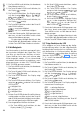
4.2 Synchronous control of multiple
spotlights (master / slave mode)
Multiple ODC-100 / RGB and PARC-100 / RGB (also
a combination of both) may be connected. The
master unit can then control all slave units in sync.
1) Connect the spotlights via their DMX jacks to
a chain. Please refer to chapter 4.3.1 “Con-
nection”, ignoring step 1.
2)
The units that are to be controlled by the mas-
ter unit must be defined as slave units:
a)
Press the button MENU repeatedly until the
highest menu level has been reached.
b) Press the button UP or DOWN repeatedly
until the display indicates .
c) Press the button ENTER and then use the
button UP or DOWN to select:
= master unit
= slave unit
3)
Any sequences of scenes that have been
stored on the master unit (chapter 4.1.5) may
be copied to the slave units:
a)
On the master unit, press the button MENU
repeatedly until the highest menu level has
been reached.
b) Press the button UP or DOWN repeatedly
until the display indicates .
c) Press the button ENTER. The display indi-
cates , , , , or
.
d) Press the button UP or DOWN repeatedly
until the display indicates .
e) Press the button ENTER so that the display
indicates four entry positions (. . . .). Then
press the following buttons:
UP, DOWN, UP, DOWN.
Each time one of these buttons is pressed,
an asterisk ( ) will appear on the display.
f) Press ENTER to start copying. During copy-
ing, the spotlight lights up in yellow. If an
error occurs, the spotlight will light up in
red. Upon successful completion, the spot-
light will light up in green.
g) To switch on the operation mode desired,
press the button MENU so that the display
indicates again. Use the buttons UP
and DOWN to select the operating mode
and then press ENTER to activate it.
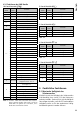
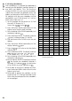
4.3 Operation with a DMX controller
DMX is short for Digital Multiplex and means
digital control of multiple DMX units via a com-
mon control line. For operation via a DMX con-
troller (e. g. DMX-1440 or DMX-510USB from
IMG STAGE LINE), the spotlight is equipped with
10 DMX control channels. However, it can, if re-
quired, also be controlled via 5, 4 or 3 channels
only. Please refer to chapter 4.3.5 for more in-
formation on channel functions and DMX values.
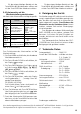
4.3.1 Connection
For DMX signal transmission, special cables should
be used (e. g. CDMXN-… from IMG STAGE LINE).
For cable lengths exceeding 150 m or for control
of more than 32 units via a single DMX output, it
is generally recommended to insert a DMX level
matching amplifier (e. g. SR-103DMX).
1)
Connect the input DMX IN to the DMX output
of the light controller or to the DMX output
of another DMX-controlled unit.
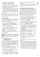
For the spotlight ODC-100 / RGB, connect
the plug (C) of the cable DMX IN to the inline
jack (D) of the supplied cable equipped with
an XLR plug. Then fasten the nut to secure
this connection.
DMX IN C
D
Fig. 4 DMX connection ODC-100 /RGB
Use an extension cable to connect the XLR
plug to the DMX output of the light controller
or, if additional DMX-controlled units are used,
to the DMX output of the last DMX-controlled
unit.
2)
Connect the output DMX OUT to the DMX
input of the second DMX unit. Connect the
output of the second DMX unit to the input
of the third DMX unit etc. until all DMX-con-
trolled units have been connected in a chain.
If the DMX connection cables between
the units are too short when interconnecting
multiple ODC-100 / RGB spotlights, use suitable
extension cables, e. g.
ODP-34DMX length: 2 m or
ODP-34DMX / 10 length: 10 m
3)
To prevent interference in signal transmission,
in case of long cables or a multitude of units
connected in series, terminate the DMX output
of the last DMX unit in the chain with a 120 Ω
resistor (> 0.3 W): Connect a corresponding