IE-iMcV-E1-Mux/4 Operation Manual
FCC Radio Frequency Interference Statement This equipment has been tested and found to comply with the limits for a Class B computing device, pursuant to Part 15 of the FCC Rules. These limits are designed to provide reasonable protection against harmful interference when the equipment is operated in a commercial environment.
Table of Contents FCC Radio Frequency Interference Statement ------------------------------------------------- ii Warranty ----------------------------------------------------------------------------------------------- ii About the IE-iMcV-E1-Mux/4 ---------------------------------------------------------------------- 1 Managed Modules----------------------------------------------------------------------------- 2 Port Interfaces -------------------------------------------------------------------------------
Normal Operation ------------------------------------------------------------------------------ 24 Fiber Optic Cleaning Guidelines------------------------------------------------------------- 25 Electrostatic Discharge Precautions--------------------------------------------------------------26 Specifications-----------------------------------------------------------------------------------------27 Standards/Compliance -----------------------------------------------------------------------------27 IMC Networ
About the IE-iMcV-E1-Mux/4 Overview The IE-iMcV-E1-Mux/4 is a media converter that transports four independent E1 lines over an existing single (or dual, “1+1”) standard 155Mbps-capable fiber optic line operating at an effective rate of 150Mbps. One serial link (RS-232) and one Ethernet (10/100BaseT) connection are also multiplexed onto the fiber link(s). Each of these communication channels is transported end-to-end at full wire speed with very low latencies.
• • • • • Local CLI management console port on a Mini Jack connector Remote management capability through iMediaChassis series AIS generation on signal loss on all E1 interfaces SNMP Alarm TRAP reporting in managed chassis MDI/MDIX automatic Ethernet port switching The IE-iMcV-E1-Mux/4 module is a dual-wide iMcV module.
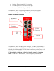
• • • Optional SFP port for optical 1+1 protection. One Mini Jack serial RS-232 serial console port One user serial RS-232 data port (RJ-45) The IE-iMcV-E1-Mux/4 is easily configured by using the serial console port connection or through an SNMP management application such as iView². Console Serial Port Connection 10/100BaseT Connector RS-232 Connector E1 RJ-48 Connectors SFP Ports Console The IE-iMcV-E1-Mux/4 includes a console serial port.
iView² Management Software iView² is the IMC Networks management software that features a GUI and gives network managers the ability to monitor and control manageable IMC Networks products. iView² is available in several versions, including WebServer version 3.0, and can also function as a snap-in module for HP OpenView Network Node Manager and other third party SNMP Management software. For assistance in selecting the right version of iView² for your operating system, please visit: http://www.imcnetworks.
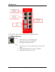
LED Operation 10/100BaseT Connector RS-232 Connector E1 RJ-48 Connectors SFP Ports The IE-iMcV-E1-Mux/4 features diagnostic LEDs as explained below.
E1 RJ-48 Connectors • • • • • ALARM: OFF during normal operation Blinks red+green simultaneously when CV errors detected on the E1 line at far end of the optical line Glows red+green when loss of service (LOS) is detected, OR continuous bit errors are detected on the E1 line at far end of the optical line Blinks red when local CV errors detected on E1 line.
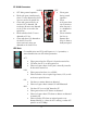
Connector Pinout and DIP Switch Assignments DIP Switch Assignments A single 10-position DIP Switch is located on the unit to set the configuration.
10/100BaseT Ethernet Mating Connector Pinout The following table lists the pin configuration for the standard RJ-45 Ethernet connector. Pin 1 2 3 4 5 6 7 8 Signal Transmit + Transmit Receive + None None Receive None None Pin 1 NOTE MDI/MDIX AutoCross function will automatically transpose the Transmit and Receive lines if required. E1 Port Mating Connector Pinout The following table lists the pin configuration for the standard RJ-48 E1 port mating connectors.
RS-232 Port Mating Connector Pinout The following table lists the pin configuration for the RS-232 port mating connector. Pin 1 2 3 4 5 6 7 8 Signal None None None Signal Ground Receive Data (in to unit) Transmit Data (out of unit) None None Pin 1 This port provides an end-to-end RS-232 line that can support up to 250K Baud and is transparent to all RS-232 protocols.
Installation Instructions Each IE-iMcV-E1-Mux/4 module requires two adjacent slots in an iMediaChassis or MediaChassis. To install the module in a chassis, remove the blank faceplates covering the slots where the module is to be installed. Then slide the module into the chassis card guides until the module is seated securely in the slots. Secure the module to the chassis by tightening the captive screw. All IE-iMcV-E1-Mux/4 units are shipped from the factory configured as Host units.
Configuration Options The following sections describe the configurable features. Use the "default" command to restore the unit's default settings. This restores the card's default configuration and resets the default username and password. User: admin / Password: admin Ethernet Line Setup If the Ethernet port is not used, it can be set to disabled via a console session or via iView², to effectively block all traffic on this port. Packet Size The Ethernet transport can accommodate packets up to 1916 bytes.
FX LinkLoss (FXLL) FX LinkLoss is a link integrity monitoring feature that forwards fiber link faults to the RJ-45 DATA port to indicate that a fiber link fault has occurred. FX LinkLoss can be enabled in iView². Link Fault Pass-Through (LFPT) Link Fault Pass-Through (LFPT) is a troubleshooting feature that passes a link fault from the Ethernet port on one module through to the Ethernet port on the other module. LFPT can be enabled via iView² or through the console port.
Loopback Each E1 port can be tested in loopback mode by enabling either a Host loopback or Remote loopback test path. This capability allows the end-user to help troubleshoot and isolate system problems such as improper/broken line terminations, cables or malfunctioning equipment. With Host loopback, the E1 copper port, connected to the Host unit, is looped back to that port within the local unit.
Console Screens Configuration Using the Console Port The following section describes configuration using the console screens. The Remote module is only configured through the Host. Login Screen After running through an initial self test, the log-in screen is displayed (the diagnostic information displayed below is for illustration purposes only and may differ from the actual screen display): The username is case sensitive with a maximum length of 16 characters.
Menu Options 1 = Refer to the Unit Configuration Screen 2 = Refer to the Port Alarm Status screen 3 = Refer to the SFP Line Status screen; SFP DDMI alarms are also displayed 4 = Refer to the Ethernet Port Configuration screen 5 = Refer to the Ethernet Port Status screen 6 = Refer to the E1 Port Configuration screen 7 = Refer to the E1 Port Status screen NOTE On all configuration screens, the title is the same as the "option" selected from the previous screen.
Unit Configuration Screen The unit configuration screen displays the names of the Host and Remote units as well as the service state, whether fiber protection is enabled and the SFP BER alarm level. In addition, the unit time can be set from this screen and the username and password can be set/reset. The screen displays the current status for items 1 through 8. For security reasons, the current username and password are not displayed.
SFP Line Status Screen The SFP Line Status screen displays the status of the Host and Remote SFP links. The detailed SFP information may be viewed by entering "1" for SFP A or "2" for SFP B. Displayed data includes the manufacturer name, code, part number and revision number. These values may not be modified. For SFP modules that support DDMI values for temperature, voltage, diode current and optical receive/transmit, levels can be obtained through SNMP Management Module.
Ethernet Port Configuration Screen The screen displays the current values for items 1 through 9 for both the Host and Remote site. Enter the number of the menu item to change its configuration, and then enter the new value(s) when prompted. Ethernet Port Status Screen This screen displays the current Ethernet port status for both the Host and Remote site.
E1 Port Configuration Screen Use this screen to access the loopback and name details for each of the four E1 ports. Enter the number of the menu item to edit, and enter the new value(s) when prompted.
E1 Port Status Screen Use this screen to display the current status for each of the four E1 ports for the Host and Remote units. Enter the number of the menu item to edit, and enter the new value(s) when prompted.
Troubleshooting • All IE-iMcV-E1-Mux/4 units are shipped configured as Host units via DIP Switch #1 = OFF. The Remote unit should be set to DIP Switch #1 = ON. Be sure to confirm that the IE-iMcV-E1-Mux/4 card is set correctly when used. • The fiber transport is independent of all other ports and should be established first. If this is not possible, a physical fiber loopback can be used for fiber port verification. A fiber loopback will cause all connected ports to loop back their respected data.
Fiber Optic Port Verification As a troubleshooting aid, the fiber optic ports can be verified by placing a physical loopback optical line on the ports and verify the LED behavior as shown: The ACT LED will arbitrarily be configured to either the A or B fiber line. The RAI LED is RED/GREEN indicating that there is something wrong at the far end of the fiber line (in this case, the remote unit is missing). The ALARM LED is RED because the E1 port is not connected.
E1 Port Verification By placing a physical loopback connection on the E1 port, a valid signal can be detected by each individual E1 port to verify its operation. Without the fiber looped, the ALARM LED for the looped E1 port will show RED/GREEN indicating there is a problem at the far end of the fiber transport (In this case the far end unit is missing) and the STAT LED is RED because the fiber is in LOS. With the fiber looped, the E1 port will only show a normal GREEN STAT LED.
Normal Operation Under normal operation the following LED display is given: GREEN LNK 10/100BaseT E1 10/100BaseT E1 RS-232 E1 RS-232 E1 E1 E1 E1 E1 GREEN STAT GREEN ACT, LNK, MSA 24
Fiber Optic Cleaning Guidelines Fiber Optic transmitters and receivers are extremely susceptible to contamination by particles of dirt or dust, which can obstruct the optic path and cause performance degradation. Good system performance requires clean optics and connector ferrules. 1. Use fiber patch cords (or connectors, as appropriate) only from a reputable supplier; low-quality components can cause many hard-to-diagnose problems in an installation. 2.
Electrostatic Discharge Precautions Electrostatic discharge (ESD) can cause damage to any product, add-in modules or stand alone units, containing electronic components. Always observe the following precautions when installing or handling these kinds of products 1. Do not remove unit from its protective packaging until ready to install. 2. Wear an ESD wrist grounding strap before handling any module or component.
Specifications Power Consumption (Typical) 0.96A @ +5 VDC Operating Temperature +32°C to +158°F (0°C to +70°C) Storage Temperature -40°F to +158°F (-40°C to +70°C) Humidity 5 to 95% (non-condensing); 0 to 10,000 ft. altitude Dimensions Dual Slot iMcV module Standards/Compliance • • • • • • IEEE 802.3x Flow Control IEEE 802.3i 10Base-T twisted pair IEEE 802.3u 100Base-TX twisted pair IEEE 802.3u 100Base-FX or SX fiber ITU G.
IMC Networks Technical Support Tel: (949) 465-3000 or (800) 624-1070 (in the U.S. and Canada); +32-16-550880 (Europe) Fax: (949) 465-3020 E-Mail: techsupport@imcnetworks.com Web: www.imcnetworks.
Definition of Terms/Acronyms The following are terms and phrases used within this manual (shown in italics), or which are found in documents associated with this equipment. 1+1 The Term “1+1” refers to line protection where identical information is transmitted on two redundant lines. The Receiver chooses the “best” line to use based on the BER of the line.
LED Light Emitting Diode: A small stack of lights to indicate link, duplex or other options. LFPT Link Fault Pass-Through: LFPT can be enabled via iView² or through the console port. LOF Loss Of Frame: An error condition where the receiver/decoder misses detection of the framing signal. LOS Loss Of Signal: An error condition where the receiving line interface unit does not detect a signal. MDI/MDIX Media-Dependent Interface/ Media-Dependent Interface Crossover.
Certifications CE: The products described herein comply with the Council Directive on Electromagnetic Compatibility (2004/108/EC). European Directive 2002/96/EC (WEEE) requires that any equipment that bears this symbol on product or packaging must not be disposed of with unsorted municipal waste. This symbol indicates that the equipment should be disposed of separately from regular household waste.
19772 Pauling • Foothill Ranch, CA 92610-2611 USA TEL: (949) 465-3000 • FAX: (949) 465-3020 www.imcnetworks.com © 2011 IMC Networks. All rights reserved. The information in this document is subject to change without notice. IMC Networks assumes no responsibility for any errors that may appear in this document. IE-iMcV-E1-Mux/4 is a trademark of IMC Networks. Other brands or product names may be trademarks and are the property of their respective companies.