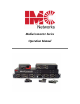
MediaConverter Series Operation Manual
FCC Radio Frequency Interference Statement MediaConverter/1 and /4 This equipment has been tested and found to comply with the limits for a Class B computing device, pursuant to Part 15 of the FCC Rules. These limits are designed to provide reasonable protection against harmful interference when the equipment is operated in a commercial environment.
Warranty IMC Networks warrants to the original end-user purchaser that this product, EXCLUSIVE OF SOFTWARE, shall be free from defects in materials and workmanship under normal and proper use in accordance with IMC Networks' instructions and directions for a period of six (6) years after the original date of purchase. This warranty is subject to the limitations set forth below.
Table of Contents FCC Radio Frequency Interference Statement ....................................................ii Warranty...........................................................................................................iii About the Modular Media Converters ................................................................1 About McPIMs ...................................................................................................1 About McLIMs .................................................
About the Modular Media Converters The Modular Media Converter Series includes modules that convert copper to singlemode or multi-mode fiber at Ethernet, Fast Ethernet and Gigabit speeds. Modular Media Converter series chassis provide power to media converter modules, and are available with one, four, eight or twelve slots for installing any combination of McPIMs (10Mbps Ethernet), McLIMs (100 Mbps Fast Ethernet), McLIM TP-TX/FX (Switching 10/100 Mbps) and McGigabit modules (1.25 Gbps Ethernet).
About McLIMs McLIMs (Media Converter Link Interface Modules) are 100 Mbps Fast Ethernet modules which provide a single-conversion between 100Base-TX twisted pair and 100Base-FX (McLIM TX/FX) or 100Base-SX (McLIM TX/SX) fiber and support Half or Full-Duplex. McLIM TP-TX/FX is an Auto Negotiating, switching media converter which offers plug-and-play operation to convert 10 Mbps or 100 Mbps, Half-or-Full-Duplex twisted pair to 100Base-FX, Full-Duplex fiber.
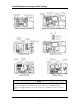
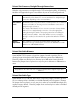
Board Diagrams and Jumper/Switch Settings NOTE To determine which board diagram matches the module (-20, -30, -40, -50, etc.), compare the jumper locations with the diagrams found above. 10/100 Switching modules and Gigabit modules sets do not require any configuration and are not shown above.
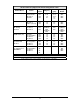
Media Converter Jumper/DIP Switch Configuration Table Feature Jumper Position ON (pins) OFF (pins) Factory Default McPIM TP/FO (-20) TP Dist. (100+ M) Shielded Cable FO LinkLoss FiberAlert JP2 JP3 JP4 JP5 one or none both 1-2 2-3 Both one or none 2-3 1-2 OFF OFF OFF OFF McPIM TP/FO (-40) FiberAlert FO LinkLoss TP Dist.
Twisted Pair Crossover/Straight-Through Connections Whether using crossover or straight-through CAT5 twisted pair cabling, all Switching Modules will support both types of connections by one of the following methods: AutoCross McLIM TX/FX (-00) and McGigabit include AutoCross, a feature that automatically selects between a crossover workstation or straight-through connection depending on the connected device.
LinkLoss, FiberAlert and Link Fault Pass-Through McPIM TP/FO and McLIM TX/FX and TX/SX include the following features: • FO/FX LinkLoss (a.k.a. "Fiber LinkLoss" or "LinkLoss") • TP/TX LinkLoss (a.k.a. "Twisted Pair LinkLoss” or "Reverse LinkLoss”) • FiberAlert and Pulsing FiberAlert FiberAlert and LinkLoss are advanced troubleshooting features that can help you locate "silent failures" on your network.
Link Integrity During normal operation, link integrity pulses are transmitted by all point-to-point Ethernet devices. When an IMC Networks media converter receives valid link pulses, it knows that the device to which it is connected is up and sending pulses, and that the copper or fiber cable coming from that device is intact. The appropriate “LNK” (link) LED is lit to indicate this.
Link Fault Pass Through Link Fault Pass Through (LFPT) is a troubleshooting feature that combines TX and FX LinkLoss from both the local and remote media converter modules (only available on the McLIM the 100 Mbps TX/FX -00, -10, -20, -30). LFPT is enabled by turning on both FX and TX LinkLoss on both modules. This feature allows both end segments of the conversion to detect link faults occurring in the media conversion chain.
Pulsing FiberAlert Pulsing FiberAlert minimizes the problems associated with the loss of one strand of fiber. If a strand is unavailable, the device at the receiver end notes the loss of link. The device will stop transmitting data and start sending link pulses. Until a valid link is received, the fiber link LED will be OFF on the device on the receiver side of the fiber strand with the fault while the fiber Link LED on the other unit will blink.
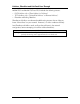
Auto Negotiation The following chart states the availability of the Auto Negotiation feature on media conversion modules.
NOTE McLIM TPTX/FX is a Plug-And-Play device, therefore Auto Negotiation is always enabled. The following table states the availability of Auto negotiation on media conversion modules.
Power Supply Installation When installing a redundant power supply module into a powered-on 12-Slot chassis, IMC Networks recommends setting the ON/OFF switch on the module (if present) to OFF. After installing the power supply, turn its switch ON. If the redundant power supply module does NOT have an ON/OFF switch, IMC Networks recommends powering-down the chassis before installing the power supply. Turn the chassis back ON after installing the power supply.
LEDs on McPIM TP/FO (-10) The LED functions on McPIM TP/FO (-10) are as follows: FO LINK/ACT TP LINK/ACT Glows green when link is established on the FO port; blinks green when activity is detected on the port. Glows amber when link is established on the TP port; blinks amber when activity is detected on the port.
LEDs on McGigabit and McLIM TX/FX and TX/SX (-00, -10, 20, 30) The LED functions on McGigabit and McLIM TX/FX and TX/SX Modules are as follows: FX LINK/ACT TX LINK/ACT ACTIVITY Glows green when link is established on the FX port; blinks green when activity is detected on the port. Glows amber when link is established on the TX port; blinks amber when activity is detected on the port. Glows green in normal operation.
Installation Troubleshooting The following information assists in troubleshooting the Modular Media Converters: • During installation, first test the fiber and twisted pair connections with all troubleshooting features disabled, then enable these features, if desired, just before final installation. This will reduce the features’ interference with testing. • When working with units where the features cannot be connect, establish BOTH the twisted pair and fiber connections in order to establish link LEDs.
Rackmount Instructions Elevated Operating Ambient If installed in a closed or multi-unit rack assembly, the operating ambient temperature of the rack environment may be greater than room ambient. Therefore, consideration should be given to installing the equipment in an environment compatible with the maximum ambient temperature (Tma) specified by the manufacturer.
Specifications Operating Temperature +32°F to +122°F (0°C to +50°C); 5% to 95% (non-condensing), 0 – 10,000 ft. altitude Storage Temperature -13°F to +158°F (-25°C to +70°C); 5% to 95% (non-condensing) *Some products may support lower operating and storage temperatures. Electrical Media Converter AC Input Load Maximum Heat Generated 1 115/230 or 120-240 VAC , 50/60Hz, 0.3A/0.15A 51 BTU/hour 4 120/240 VAC , 50/60Hz, 1A/0.5A 67 BTU/hour 8 120/240 or 100-240 VAC, 50/60Hz, 1.6/0.
Fiber Optic Cleaning Guidelines Fiber Optic transmitters and receivers are extremely susceptible to contamination by particles of dirt or dust, which can obstruct the optic path and cause performance degradation. Good system performance requires clean optics and connector ferrules. 1. Use fiber patch cords (or connectors, if you terminate your own fiber) only from a reputable supplier; low-quality components can cause many hard-to-diagnose problems in an installation. 2.
Safety Certifications UL/CUL: Listed to Safety of Information Technology Equipment, including Electrical Business Equipment. CE: The products described herein comply with the Council Directive on Electromagnetic Compatibility (2004/108/EC) and the Council Directive on Electrical Equipment Designed for use within Certain Voltage Limits (2006/95/EC). Certified to Safety of Information Technology Equipment, Including Electrical Business Equipment. For further details, contact IMC Networks.
19772 Pauling • Foothill Ranch, CA 92610-2611 USA TEL: (949) 465-3000 • FAX: (949) 465-3020 www.imcnetworks.com © 2010 IMC Networks. All rights reserved. The information in this document is subject to change without notice. IMC Networks assumes no responsibility for any errors that may appear in this document. MediaConverter Series is a trademark of IMC Networks. Other brands or product names may be trademarks and are the property of their respective companies.