SNMP Management Module Operation Manual
FCC Radio Frequency Interference Statement This equipment has been tested and found to comply with the limits for a Class B computing device, pursuant to Part 15 of the FCC Rules. These limits are designed to provide reasonable protection against harmful interference when the equipment is operated in a commercial environment.
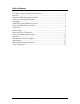
Table of Contents FCC Radio Frequency Interference Statement ........................................................ ii Warranty................................................................................................................ ii About the SNMP Management Module..................................................................1 Installing the Management Module ........................................................................1 Configuring ................................................
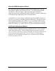
About the SNMP Management Module The SNMP Management Module includes two twisted pair ports, one for management and one reserved for future use. The Management Module also features a DB-9 serial port. Both twisted pair ports include the AutoCross feature that automatically selects between a crossover workstation or straight-through, depending on the connected device. An iMediaChassis series with an installed Management Module connects to the LAN via an external 10/100 twisted pair connection.
SNMP Management Module LEDs Each SNMP Management Module features several LEDs. The LED functions are: Glows green when a link is established on port. LNK/ACT Glows green when data activity occurs. FDX/COL Blinks amber when port is in Full-Duplex mode. Blinks amber when collisions occur; extinguished when port is operating in Half-Duplex mode. TEMP Glows yellow when temperature of unit surpasses a user-defined Level, configurable through iView². PS Glows amber when one power supply malfunctions.
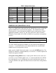
VLANS Modes IP Subnet Mask Default Gateway Bandwidth Software Updates TABLE: Configuration Options IView2 Serial Telnet 9 9 9 9 9 9 9 9 9 9 9 9 9 9 9 9 9 TFTP 9 9 TFTP iConfig 9 9 9 9 SNMP Write Lock (iMediaChassis series) There is an SNMP Write Lock switch on the iMediaChassis series; check the specific iMediaChassis manual for the location. The SNMP Write Lock switch prevents a new Management Module from re-configuring an iMcVapplication module’s settings (e.g.
1. Open a session in iConfig with a device you want to administer. 2. Choose the Administration tab. 3. Click the Save PROM File button. 4. The Save as PROM dialog box appears. 5. Choose a folder and then select the filename you wish to save. NOTE .BIN is the default extension. 6. Click the Save button to save, the file is saved. 7. Add entries to the Notes box, if desired; then click OK. If you do not wish to enter Notes, click Close. 8. Click OK to close Succeeded dialog box. (Prom Save was successful.
. After rebooting, set the SNMP Write Lock switch back to NORMAL. The previously made settings to the application modules will be active. NOTE When removing an SNMP card with the SNMP Write Lock enabled (set to LOCKED), current application modules settings will not be changed. Never power-cycle the chassis while the SNMP Write Lock is enabled (except during Step 5 in the preceding process). This will revert the SNMP card back to its original factory settings.
About iConfig iConfig is an in-band configuration utility (in iView²) that lets users quickly and easily complete the first stages of SNMP configuration for SNMPmanageable devices. iConfig can set the IP address, subnet mask and default gateway as well as define the community strings and SNMP traps. In addition to the above functions, iConfig offers an authorized IP address system and access restriction to MIB groups supported by manageable devices.
the iView² CD. For information regarding the use of the iConfig utility, refer to the iConfig utility help file. About Serial Port Configuration The SNMP Management Modules used with the iMediaChassis series feature a serial port that includes a DB-9 serial connector. To connect an iMediaChassis series to a terminal/computer, use a straight-through (pin-topin) cable. If the computer/terminal’s port is not compatible with a DB-9 COM port, use the pin connection chart for reference in making a cable.
Saved Values This section displays changes made during current session: • IP Address (MUST be assigned during initial configuration) • Subnet Mask (MUST be assigned during initial configuration) • Default Gateway Current Values This section displays values currently in use: • IP Address (IP address of SNMP agent) • Subnet Mask (mask to define IP subnet agent is connected to) • Default Gateway (default router for IP traffic outside subnet) Command List This section displays the commands available: • I = Ente
device, pressing Enter after each. The default gateway can also be assigned, if desired (press Enter to skip). When finished, press Enter, then type reboot for changes to take effect. The Saved Values and Current Values should now display both the changes made (e.g., new IP address and subnet mask). Creating Community Strings for SNMP The purpose of community strings is to add a level of security to a network. The default community string is named "public" and has read/write access.
function enables ALL of the traps. To selectively activate and deactivate traps, use iConfig. iConfig Traps allow greater control using the Trap Edit than the serial and Telnet does. To choose generic or enterprise-specific Traps, use iConfig. Removing Trap Destinations To remove all trap destinations, press K. Press Y to remove all trap destinations. Press N to abort and then press Enter. Change Serial Password The serial configuration does not have a default password; it is optional.
If the download is interrupted, do not reset the module or reboot the SNMP Management Module; doing so can corrupt the PROM and render the module useless. Close the session and then open a new TFTP session. Additional Device-Specific Options The iMediaChassis series also includes device-specific options. Press the Space Bar when in the Command List section of the Main Configuration screen (serial configuration/Telnet session), type the name of the action, and press Enter.
Downloading Files Refer to Device-Specific Options— Downloading Files. Using iView² iView² is a network management application for IMC Networks’ intelligent networking devices. It features a graphic user interface (GUI) and gives network managers the ability to monitor and control products from a variety of platforms. Using iView² with HP OpenView During the installation, the iView² application will ask if HP OpenView is installed on the management PC. Click Yes to integrate the appropriate files.
UMA (Unified Management Agent) Centralized management makes practical sense for networks of all sizes, especially service provider networks that must monitor and upgrade large quantities of devices. The Unified Management Agent (UMA) allows operators to manage all IMC modules with on-board logic (FiberLinX-II series) installed in an IMC Networks iMediaChassis series, with a single IP address from a central location.
Easy Upgrades with the Unified Management Agent • Upgrade one or multiple Host (CO) or Remote (CPE) devices with just a few mouse clicks. Refer to the iMcV-FiberLinX-II, iMcV-GigaFiberLinX, AccessEtherLinX and IE-Mini FiberLinX-II series manuals for complete information. • All devices in chassis are fully functional while upgrades are in process. • Manage up to 41 devices with a single IP address. • Telnet access and view for all system devices.
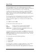
Telnet Session With the Unified Management Agent, users can also manage multiple devices installed in, or connected to, an iMediaChassis via a Telnet session, as well as assigning an IP address. In the example below, the devices listed on the left (e.g. MetroFiber 3 represent Host iMcV-FiberLinX-II units while the devices listed on the right (Irvine POP 3) represent Remote iMcV-FiberLinX-II units.
System Requirements To run iView², the management PC must be equipped with the following: • 29 MB free disk space, 64 MB RAM • Windows NT 4.0 Service Pack 5, 2000 Professional, XP Professional • Microsoft SNMP Services Installed • Microsoft IE 4.0 or Higher • Microsoft IIS required for Web Server Version Java versions require the following: • 25 MB free disk space, 64 MB RAM • Any OS capable of running Java (Windows 98 or above, Solaris, LINUX) • Java Runtime v 1.
IMC Networks Technical Support Tel: (949) 465-3000 or (800) 624-1070 (in the U.S. and Canada); +32-16-550880 (Europe) Fax: (949) 465-3020 E-Mail: techsupport@imcnetworks.com Web: www.imcnetworks.
Electrostatic Discharge Precautions Electrostatic discharge (ESD) can cause damage to your add-in modules. Always observe the following precautions when installing or handling an add-in module or any board assembly. 1. Do not remove unit from its protective packaging until you’re ready to install it. 2. Wear an ESD wrist grounding strap before handling any module or component.
Safety Certifications UL/CUL: Listed to Safety of Information Technology Equipment, including Electrical Business Equipment. CE: The products described herein comply with the Council Directive on Electromagnetic Compatibility (89/336/EEC) and the Council Directive on Electrical Equipment Designed for use within Certain Voltage Limits (73/23/EEC). Certified to Safety of Information Technology Equipment, Including Electrical Business Equipment. For further details, contact IMC Networks.
Notes 20
19772 Pauling • Foothill Ranch, CA 92610-2611 USA TEL: (949) 465-3000 • FAX: (949) 465-3020 www.imcnetworks.com © 2008 IMC Networks. All rights reserved. The information in this document is subject to change without notice. IMC Networks assumes no responsibility for any errors that may appear in this document. IE-MediaChassis/2 is a trademark of IMC Networks. Other brands or product names may be trademarks and are the property of their respective companies.