
Instruction manual


15
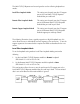
Remote Fiber Loopback Mode
To set the loopback testing mode to Remote Fiber Loopback Mode, perform the
following:
1.
Set the Local iMcV-T1/E1/J1 Repeater module Loopback to
None
(DIP Switch S3-3=On and S3-4=On)
2.
Set the Remote iMcV-T1/E1/J1 Repeater module to
Local
Loopback
(DIP Switch S3-3=Off and S3-4=On).
This configuration allows the user to test the path from the CO copper port to the
Remote iMcV-T1/E1/J1 Repeater module fiber port and loop it back. The transmitted
data is sent unhindered and the received data is ignored.
Remote Copper Loopback Mode
To set the loopback testing mode to Remote Copper Loopback Mode, perform the
following:
1.
Set the Local iMcV-T1/E1/J1 Repeater module Loopback to
None
(DIP Switch S3-3=On and S3-4=On)
2.
Set the Remote iMcV-T1/E1/J1 Repeater module to
Analog
Loopback
(DIP Switch S3-3=On and S3-4=Off).
This configuration allows the user to test the path from the CO copper port to the
Remote iMcV-T1/E1/J1 Repeater module copper port and loop it back. The
transmitted data is sent unhindered and the received data is ignored.
After the user has confirmed the integrity of these data paths, the user can activate
the PRBS data generator on the Remote module and place a loopback on the
customer premise equipment to test the final copper segment (refer to the Testing
with
PRBS section for more information).