iMcV-T1/E1/J1 Repeater Operation Manual
FCC Radio Frequency Interference Statement This equipment has been tested and found to comply with the limits for a Class A computing device, pursuant to Part 15 of the FCC Rules. These limits are designed to provide reasonable protection against harmful interference when the equipment is operated in a commercial environment.
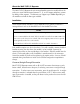
Table of Contents FCC Radio Frequency Interference Statement ....................................................ii Warranty............................................................................................................ii About the iMcV-T1/E1/J1 Repeater.....................................................................4 Installation .........................................................................................................4 Configuration ........................................
About the iMcV-T1/E1/J1 Repeater The iMcV-T1/E1/J1 Repeater chassis mounted media conversion module allows the end user to extend the distances between T1, J1, and E1 copper telephony systems by adding a fiber segment. The distances can support up to 100km depending on the module used and the fiber type available. Installation At the central location the iMcV-T1/E1/J1 Repeater unit is typically installed in a managed chassis such as the iMediaChassis or the MediaChassis series.
Configuration The iMcV-T1/E1/J1 Repeater module is factory-configured to use the following default features: T1/E1 Mode Receive Equalizer Gain Limit (EGL) Line Encoding Transmit LIU Waveshape (Build-out) Receive LIU Termination Transmit Data Source Jitter Attenuator Select Remote Management Loopback Selection Monitor/Boost Mode NRZ Selection T1 -30 dB (Limited Long Haul) AMI (Passive Mode) DSX-1 (0 to 133 ft) 0 dB CSU Receive Side 100 ohms Enabled Standard Data Place Jitter Attenuator on TX Side Remote Man
NOTE The iMcV-T1/E1/J1 Repeater modules are delivered pre-configured for standard T1 operation in Passive mode. To enable remote management, the user must move DIP Switch S2-2 to the “ON” position on the Remote module (refer to the DIP Switch diagram and table). Managed Modules To manage iMcV-DS3/E3/STS modules, an SNMP agent must be present; the iMediaChassis requires an SNMP management module.
Unmanaged Modules Before installing the iMcV-T1/E1/J1 Repeater module into an unmanaged chassis, configure the module hardware-selectable features via DIP Switches located at position S3 and S2 on the PCB (refer to the DIP Switch Table section for more information). The jumpers located at positions JP1 and JP2 are factory configured— DO NOT CHANGE. Description of DIP Switch-Selectable Options The iMcV-T1/E1/J1 Repeater module includes movable DIP Switches for hard switching the optional features.
Receive LIU Termination (Line Termination) This option allows the user to set the receive termination. This is used to properly terminate cables in order to prevent signal reflections which can cause signal degradation. Transmit Data Source This option allows the user to set the module to send normal data (default) or to send specific test-patterns of data to determine problems along the cable as a diagnostic tool.
Remote Management This option allows the user to enable Remote management on the module. The remote management feature is designed to work only on the remote module of the Local/Remote pair. With Remote management enabled, the user can easily perform the following: • Test the line integrity of the remote copper port. • Use the Local unit to configure all SNMP-configurable features for both units. • Use the Local unit to download firmware for both units.
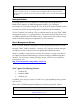
Switch Settings for Switch S2 T1/E1 Selection S2-1: OFF S2-1: ON T1 Mode Selected E1 Mode Selected default Receive Equalizer Gain Limit (EGL) iVIEW2 iVIEW2 iVIEW2 iVIEW2 iVIEW2 iVIEW2 E1 S2-2: ON -12 dB (Short Haul) S2-2: OFF -43 dB (Long Haul) T1 S2-2: ON -36 dB (Long Haul) S2-2: OFF -30 dB (Limited Long Haul) default iVIEW2 Line Encoding iVIEW2 S2-3: ON HDB3 (E1) / B8ZS (T1) S2-3: OFF AMI (Required for Passive Mode) iVIEW2 iVIEW2 default Transmit LIU Waveshape (Build-out) SWITCH S2 E1 S2-4: ON
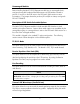
Switch Settings for Switch S3 Jitter Attenuator Select S3-1: ON S3-1: OFF Place Jitter Attenuator on RCV Side Place Jitter Attenuator on XMT Side default Remote Management S3-2: ON S3-2: OFF Remote Management Enabled (only at the REMOTE end) Remote Management Disabled (only at the LOCAL end) default SWITCH S3 Loopback Selection iVIEW2 S3-3: ON S3-3: OFF S3-3: ON S3-3: OFF S3-4: ON S3-4: ON S3-4: OFF S3-4: OFF None Local Loopback Analog Loopback Remote Loopback iVIEW2 iVIEW2 iVIEW2 iVIEW2 default
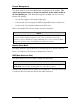
Module LED Functions This section describes the LEDs and their functions. The Fiber port LED RM is the only LED that should be lit on the modules under normal operating conditions. Copper Port LEDs LPBK Glows green when the module is set to one of the Loopback modes. NO LNK Glows green when a UTP link is NOT established. PBEO Only used when the Transmit Data Source option is set to PRBS.
Testing To test a media converter by itself, first make sure there is an appropriate fiber patch cable, then perform the following steps: 1. Connect the media converter to the T1/E1 device with a standard UTP cable. If the NO LNK LED for the copper port remains on, a valid signal is not being received. Push the crossover push button on the front of the unit. Verify that the NO LNK LED for the copper port is off. 2.
The iMcV-T1/E1/J1 Repeater can be configured to use the following loopback test modes: Local Fiber Loopback Mode This setting tests the path from the CO copper port to the Local iMcV-T1/E1/J1 Repeater module fiber port and back. Remote Fiber Loopback Mode This setting tests the path from the CO copper port to the Remote iMcV-T1/E1/J1 Repeater module fiber port and loops it back.
Remote Fiber Loopback Mode To set the loopback testing mode to Remote Fiber Loopback Mode, perform the following: 1. Set the Local iMcV-T1/E1/J1 Repeater module Loopback to None (DIP Switch S3-3=On and S3-4=On) 2. Set the Remote iMcV-T1/E1/J1 Repeater module to Local Loopback (DIP Switch S3-3=Off and S3-4=On). This configuration allows the user to test the path from the CO copper port to the Remote iMcV-T1/E1/J1 Repeater module fiber port and loop it back.
Testing with Pseudorandom Bit Sequence (PRBS) To test the copper segment from the Remote module to the Customer Premises Equipment (CPE) by using PRBS, perform the following: 1. Set the CPE to loopback the signal. 2. Set the Remote module to generate PRBSs (DIP Switch S2-9=On and S2-10=Off). Check the LEDs to verify errors are not received (refer to the Module LED Functions section for more information). Fiber Optic Specifications For fiber optic specifications, visit our Web site at www.imcnetworks.
Specifications Power Consumption (Typical) 0.550 Amp @ 5V Operating Temperature 32° to 122° F (0° to 50° C) Storage Temperature 0° to 160°F (-20° to 70° C) Humidity 5 to 95% (non-condensing); 0 to 10,000 ft. altitude Dimensions Single Slot iMcV module IMC Networks Technical Support Tel: (949) 465-3000 or (800) 624-1070 (in the U.S. and Canada); +32-16-550880 (Europe) Fax: (949) 465-3020 E-Mail: techsupport@imcnetworks.com Web: www.imcnetworks.
Fiber Optic Cleaning Guidelines Fiber Optic transmitters and receivers are extremely susceptible to contamination by particles of dirt or dust, which can obstruct the optic path and cause performance degradation. Good system performance requires clean optics and connector ferrules. 1. Use fiber patch cords (or connectors, if you terminate your own fiber) only from a reputable supplier; low-quality components can cause many hard-to-diagnose problems in an installation. 2.
Safety Certifications UL/CUL: Listed to Safety of Information Technology Equipment, including Electrical Business Equipment. CE: The products described herein comply with the Council Directive on Electromagnetic Compatibility (2004/108/EC) and the Council Directive on Electrical Equipment Designed for use within Certain Voltage Limits (2006/95/EC). Conforms to UL Std. 60950-1; Certified to CSA Std. C22.2 No.
19772 Pauling • Foothill Ranch, CA 92610-2611 USA TEL: (949) 465-3000 • FAX: (949) 465-3020 www.imcnetworks.com © 2009 IMC Networks. All rights reserved The information in this document is subject to change without notice. IMC Networks assumes no responsibility for any errors that may appear in this document. iMcV-T1/E1/J1 is a trademark of IMC Networks. Other brands or product names may be trademarks and are the property of their respective companies.