
Instruction manual

7
product that has 1550 xmt and 1310 rcv, e.g., McGigabit, TX/SSFX-SM1550-SC. The
two connected products must also have the same speed and distance capabilities
(i.e., both are single-mode [20km] or both are single/PLUS [40km]).
Twisted Pair Crossover/Pass-Through Connections
iMcV-Gigabit Modules support both crossover and straight-through Cat5 twisted pair
cabling types of connections with AutoCross a feature which automatically selects
between the two, depending on the connected device.
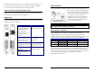
LED Operation
Each iMcV-Gigabit Module features diagnostic LEDs (see diagram below) that provide
information on features and ports.
iMcV-Gigabit (-10) iMcV-Gigabit (-00)
LNK/ACT–
glows green
when a twisted pair link
is established. Blinks
green when data is
detected on the port.
Located on RJ-45
connector.
ACT–
glows amber when
data is detected on the
port.
FDX–
glows amber when
port is operating in Full-
Duplex mode. Located
on RJ-45 connector.
LNK–
glows green when a
twisted pair link is
established.
TX LL–
glows green when
TX LinkLoss is enabled on
the port.
FDX–
glows green when
operating in Full-Duplex
mode.
LNK–
glows green when
fiber link.
MASTER–
glows amber
when operating as a
Master.
FA–
glows green when
FiberAlert is enabled.
4
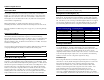
What Is FiberAlert?
FiberAlert minimizes the problems associated with the loss of one strand of fiber. If a
strand is unavailable, the IMC Networks device at the receiver end notes the loss of
link. The device will then stop transmitting data
and the link signal until a signal or link pulse is
received. The result is that the link LED on both
sides of the fiber connection will go out
indicating a fault somewhere in the fiber loop.
Using FiberAlert, a local site administrator is
notified of a fault and can quickly determine
where a cable fault is located.
WARNING
Enable FiberAlert on one side of a media conversion only. Enabling it on both
sides would keep both transmitters off indefinitely.
Using FiberAlert and LinkLoss
Modules ship from the factory with troubleshooting features disabled. Refer to the
configuration instructions on pages 5-6 of this manual, or the help file to
enable/disable this feature. The following chart provides an overview of the
troubleshooting features, their functionality and the recommended settings for a pair
of media converters in a typical central/main site to remote site application:
LinkLoss/FiberAlert Compared
Feature Fault Location Disabled LEDs Enable at
TX LinkLoss
Twisted Pair Fiber
Remote site only
FiberAlert
Fiber Fiber
Remote site only
For more information on LinkLoss/FiberAlert, visit the IMC Networks Web site at
http://www.imcnetworks.com/support/ If you are unsure of how best to implement
these features in your configuration, contact IMC Networks technical support at (800)
624-1070 (U.S./Canada), +32-16-550880 (Europe) or via e-mail at:
techsupport@imcnetworks.com.