
Instruction manual

3
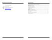
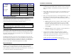
DIP Switch Configuration Chart
Module Feature DIP Switch on S1 Default
Duplex Setting 1
ON (FDX)
Master/Slave 2
OFF (Slave)
iMcV-Gigabit
-00 board
FiberAlert 4
OFF
Forced/Preferred 1
ON
Master/Slave 2
ON
TX LinkLoss 3
OFF
FiberAlert 4
OFF
iMcV-Gigabit
-10 board
FX Auto-Negoitation 5
OFF
About LinkLoss and FiberAlert
iMcV-Gigabit modules include the troubleshooting features FiberAlert and TX
LinkLoss that help locate
silent failures
on your network. It is vital that you
understand how FiberAlert and LinkLoss work, and how they will react in your
network configuration, before attempting to install the module(s).
WARNING
Installing modules without understanding the effects of LinkLoss and FiberAlert
can cause functioning units to appear flawed or even dead.
About Link Integrity
During normal operation, link integrity pulses are transmitted by all point-to-point
Ethernet devices. When an IMC Networks media converter receives valid link pulses,
it knows that the device to which it is connected is up and sending pulses, and that
the copper or fiber cable coming from that device is intact. The appropriate “LNK”
(link) LED is lit to indicate this.
The IMC Networks media converter also sends out link pulses from its copper and
fiber transmitters, but normally has no way of knowing whether the cable to the other
device is intact and the link pulses are reaching the other end. The combination of
FiberAlert and LinkLoss allows this information to be obtained, even when physical
access to a remote device (and its link integrity LED) is not available.
What is TX LinkLoss?
TX LinkLoss is a troubleshooting feature. When a fault occurs on the twisted pair
segment of a conversion, TX LinkLoss detects the fault and passes this information to
the fiber segment. If a media converter is not receiving a twisted pair link, TX
LinkLoss disables the transmitter on the media converter's fiber port. The result is in a
loss of the link on the device connected to the fiber port.
8
Installation Troubleshooting
•
During installation, first test the fiber and twisted pair connections with all
troubleshooting features disabled, then enable these features, if desired, just
before final installation. This will reduce the features’ interference with
testing.
•
When working with units where the features cannot be disabled, you must
establish BOTH your twisted pair and fiber connections before the link
LEDs will light.
•
When connecting the fiber interface of an iMcV-Gigabit module (-00) to the
fiber interface of a Gigabit switch (with fixed configuration or modular
design, GBIC/SFP), you may experience difficulty establishing a link. Please
check the following:
o
Solution 1–
Within the switch configuration (either via SNMP or a CLI),
ensure that the setting for the fiber port in use is set to 1000 Mbps,
Full-Duplex. Manually setting the switch port will result in normal
operation and a link will be established. Also, ensure auto-negotiation
is switched OFF.
o
Solutions 2–
Within the switch configuration, ensure that IEEE 802.3x
Flow Control is disabled for the Gigabit port in use.
•
If using a high powered device (which is designed for long distance
installations) for a short distance installation, the fiber transmitters may
overdrive the receivers and cause data loss. If this is the case, you may
need to add an optical attenuator to your connection.
For fiber specifications, visit the IMC Networks Web site at
www.imcnetworks.com/adocs/fcs.asp
or contact IMC Networks for more
information.