
Specifications


➤ Make sure that DIP switches are configured correctly. If used in pairs,
make certain that the FiberLinX TX/FX at the host site is configured as
Host (Master) with DIP switch
7 OFF and DIP switch 8 ON on switch
S1. Also make certain that the management DIP switches are config-
ured as desired. (See page 3, SNMP Management Traffic DIP Switches.)
LED Indicators
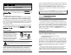
FiberLinX TX/FX features diagnostic LEDs for each port. The following illus-
tration shows the location of the LEDs on FiberLinX TX/FX.
LEDS FOR THE FX DATA PORT
LED functions for the FX data port are as follows:
FDX
Glows yellow when Full-Duplex is selected on port.
ACT
Blinks green when data is detected on the port.
LNK
Glows green when a link is established.
FA
Glows green when FiberAlert is enabled.
LEDS FOR THE
TX DATA PORT
LED functions for the TX data port are as follows:
LNK
Glows green when a link is established.
FDX
Glows yellow when Full-Duplex is selected on the port.
LEDS FOR THE TX MANAGEMENT PORT
LED functions for the TX management port are as follows:
LNK
Glows green when a link is established.
FDX
Glows yellow when Full-Duplex is selected on the port.
FAR CPU UP
Glows yellow when far end is detected.
FAR TX LINK
Glows green when a link is established on remote (far-end)
TX data port.
SNMP
Blinks green with SNMP activity.
TX ACT
Blinks green with twisted pair activity.
Note: The FAR CPU UP LED and the FAR TX LNK LED only function when two
FiberLinX TX/FX are connected to one another (i.e., Host and Remote).
Note: Although the management port is designed to accept SNMP traffic, ANY port on the
FiberLinX TX/FX Module can be configured to serve as the SNMP management port
13
IMC N
ETWORKS TECHNICAL SUPPORT
Tel
: (949) 465-3000 or (800) 624-1070 (in the U.S. and Canada);
+32-16-550880 (Europe)
Fax
: (949) 465-3020
E-Mail
:
techsupport@imcnetworks.com
Web
:
www.imcnetworks.com
SPECIFICATIONS
Environmental
Operating Temperature:32° - 104° F (0° - 40° C)
Storage Temperature:0° - 160° F (-20° - 70° C)
Humidity: 5 - 95% (non-condensing)
Electrical
Module: 5V ±5%, 2.0 Amp.
Heat Generation: 50 BTU/hr
FIBER OPTIC CLEANING GUIDELINES
Fiber Optic transmitters and receivers are extremely susceptible to contamination by parti-
cles of dirt or dust which can obstruct the optic path and cause performance degradation.
Good system performance requires clean optics and connector ferrules.
1) Use fiber patch cords (or connectors, if you terminate your own fiber) only from a rep-
utable supplier; low quality components can cause many hard-to-diagnose problems in
an installation.
2) Dust caps are are installed at IMC Networks to ensure factory-clean optical devices.
These protective caps should not be removed until the moment of connecting the fiber
cable to the device. Assure that the fiber is properly terminated, polished and free of
any dust or dirt and that the location is as free from dust and dirt as possible.
3) Store spare caps in a dust-free environment such as a sealed plastic bag or box so that
when reinstalled they do not introduce any contamination to the optics.
4) Should it be necessary to disconnect the fiber device, reinstall the protective dust caps.
5) If you suspect that the optics have been contaminated, alternate between blasting with
clean, dry compressed air and flushing with methanol to remove particles of dirt.
E
LECTROSTATIC DISCHARGE PRECAUTIONS
Electrostatic discharge (ESD) can cause damage to your add-in modules. Always observe
the following precautions when installing or handling an add-in module or any board assem-
bly.
1) Do not remove unit from its protective packaging until you’re ready to install it.
2) Wear an ESD wrist grounding strap before handling any module or component. If you
do not have a wrist strap, maintain grounded contact with the system unit throughout
any procedure requiring ESD protection.
WARNING! Integrated circuits and fiber optic components are extremely susceptible
to electrostatic discharge damage. Do not handle these components directly unless
you are a qualified service technician and use tools and techniques that conform to
accepted industry practices.
3) Hold boards by the edges only; do not touch the electronic components or gold con-
nectors.
14