
Specifications


Example 2
FIBER CONVERSION AND HIGHLY SECURE REMOTE
M
ANAGEMENT BETWEEN TWO COPPER
-BASED
SWITCHES
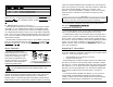
For the highest level of management security, route SNMP management
traffic completely away from the switch. Two FiberLinX TX/FX units are also
used in this configuration. The following illustration shows an external hub
being used to maintain LAN separation.
Central Site
Switch
Switch
Hub
Switch
Switch
Hub
SNMP Management
Traffic
Remote Site
Mgmt.
Port
Mgmt.
Port
(unused)
11
NOTE
You can access and manage the Remote site’s FiberLinX TX/FX directly in
this configuration if you assign the unit an IP address.
Example 2: DIP Switch Settings
Switch 7 Switch 8 Switch 1 Switch 2 Switch 3
(S1) (S1) (S3) (S3) (S3)
Central (Host) OFF ON ON OFF OFF
Remote ON OFF OFF OFF OFF
Example 3
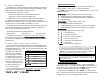
DIRECT FIBER SWITCH CONNECTION FROM CENTRAL
TO
REMOTE SITE
To achieve remote management and monitoring capabilities, directly con-
nect a FiberLinX TX/FX to a fiber-based switch. All SNMP management traffic
and data traffic goes straight into the switch at the Central site via the fiber
port. SNMP management traffic is imbedded within the corporate network,
but no management data passes to the Remote site.
Configure FiberLinX TX/FX to accept SNMP management traffic from the
fiber port. In this application, FiberLinX TX/FX is neither a Host nor Remote
unit. The twisted pair management port on this FiberLinX TX/FX is unused.
Troubleshooting
➤ If FiberLinX TX/FX is connected to a non-negotiating device, sometimes
the Duplex mode will not auto-negotiate. This can be fixed by
changing the settings in iView.
Switch
Switch
SNMP Management Traffic
Central Site
Remote Site
Mgmt.
Port
(unused)
12
Example 3: DIP Switch Settings
Switch 7 Switch 8 Switch 1 Switch 2 Switch 3
(S1) (S1) (S3) (S3) (S3)
OFF OFF OFF OFF ON