
Instruction manual

4
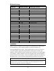
DIP Switch Settings
FUNCTION SWITCH SETTINGS RESULT [(D) = Default]
Loopback (iView
2
Configurable)
S1-1: OFF Loopback Disabled (D)
S1-1: ON Loopback Enabled
Loopback Type (iView
2
Configurable)
S1-2: OFF Coax (D)
S1-2: ON Fiber
Jitter Attenuation (iView
2
Configurable)
S1-3: OFF Jitter Attenuator on Receive Side
S1-3: ON Jitter Attenuator on Transmit Side (D)
FiberAlert (iView
2
Configurable)
S1-4: OFF FiberAlert Disabled (D)
S1-4: ON FiberAlert Enabled
Line Build-Out (iView
2
Configurable)
S1-5: OFF 0 to 255 ft.
S1-5: ON > 255 ft. (D)
Transmit Data Source (iView
2
Configurable)
S1-6: ON 7: ON Standard Data (D)
S1-6: OFF 7: ON Unframed All Ones
S1-6: ON 7: OFF Alternating Ones & Zeros
S1-6: OFF 7: OFF Pseudorandom Bit Sequence
DS3/E3/STS Selection
S1-8: ON 9: OFF 45 Mbps (DS3)
S1-8: OFF 9: ON 34 Mbps (E3)
S1-8: ON 9: ON 52 Mbps (STS)
Remote Management
S1-10: OFF Remote Management Disabled (D)
S1-10: ON Remote Management Enabled
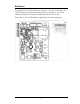
Installation
iMcV-DS3/E3/STS modules can be installed in any iMediaChassis, MediaChassis
or IE-MediaChassis series (remote modules can also be installed in any
unmanaged MediaChassis series). Each module requires one slot in the chassis.
To install a module, remove the blank brackets covering the slots where the
module is to be installed (if present) by removing the screws on the outside edges
of the bracket. Slide the module into the chassis card guides, until the module is
securely seated in the connector. Secure the module to the chassis by tightening
the captive screw. Save any blanks removed during installation for future use.
NOTE
It is not recommended that the iMcV-DS3/E3/STS module be installed in an 850-33100.
The power source in this chassis is not isolated, and cannot support positive reference
ground systems typically used in Telco environments.