iMcV-DS3/E3/STS Repeater Operation Manual
FCC Radio Frequency Interference Statement This equipment has been tested and found to comply with the limits for a Class B computing device, pursuant to Part 15 of the FCC Rules. These limits are designed to provide reasonable protection against harmful interference when the equipment is operated in a commercial environment.
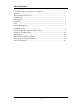
Table of Contents FCC Radio Frequency Interference Statement ....................................................ii Warranty............................................................................................................ii About the iMcV-DS3/E3/STS ............................................................................. 1 Configuration .................................................................................................... 1 DIP Switches..........................................
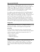
About the iMcV-DS3/E3/STS iMcV-DS3/E3/STS is an SNMP-manageable module which converts thin coax signals to single-mode or multi-mode fiber signals at a data rate of 45 Mbps (DS3), 34 Mbps (E3) or 52 Mbps (STS). Each iMcV-DS3/E3/STS, BNC/FX module includes one pair of BNC connectors and one pair of ST or SC fiber optic connectors. This module must be installed in either, an SNMP-manageable iMediaChassis chassis or an unmanaged MediaChassis chassis.
Use the Graphical User Interface (GUI) to enable features by using the iView2 SNMP management software. In a managed chassis, the software settings take priority over the SNMP enabled feature DIP Switch settings. Make sure that the software settings match the desired configuration requirements for the installation. iView² Management Software iView² is the IMC Networks management software designed specifically for the IMC Networks “iMcV” family of modules.
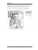
DIP Switches The iMcV-DS3/E3/STS DIP Switches are located on S1 and S2 on the PCB. The S2 DIP Switches are factory configured and must not be moved. The S1 DIP Switches provide control over the available iMcV-DS3/E3/STS features.
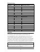
DIP Switch Settings FUNCTION SWITCH SETTINGS RESULT [(D) = Default] 2 Loopback (iView Configurable) S1-1: OFF S1-1: ON Loopback Type (iView2 Configurable) S1-2: OFF S1-2: ON Jitter Attenuation (iView2 Configurable) S1-3: OFF S1-3: ON FiberAlert (iView2 Configurable) S1-4: OFF S1-4: ON Line Build-Out (iView2 Configurable) S1-5: OFF S1-5: ON Transmit Data Source (iView2 Configurable) S1-6: ON 7: ON S1-6: OFF 7: ON S1-6: ON 7: OFF S1-6: OFF 7: OFF DS3/E3/STS Selection S1-8: ON 9: OFF S1-8: OFF 9: ON S1-8:
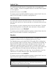
LEDs The iMcV-DS3/E3/STS module features several diagnostic LEDs per port. The LED functions are as follows: LEDs Next to Coax (BNC) Port LPBK Glows green when module is in a Loopback mode. NO LNK Glows green when a link is NOT established. PBEO When Transmit Data Source is set to Pseudorandom Bit Sequence, this LED will glow yellow when iMcV-DS3/E3/STS receives a Pseudorandom Bit Sequence with errors. The LED stays off when the converter receives a Pseudorandom Bit Sequence without errors.
Loopback Type This switch controls which data line is looped back when the Loopback DIP Switch is enabled. The data line loopback selection can be either Fiber Loopback or Coax Loopback. By default this feature is set to COAX. This feature can be controlled by SNMP management software (iView2) when the iMcV-DS3/E3/STS module is installed in a managed chassis. Jitter Attenuation This switch selects the jitter attenuation location on the coax transceiver.
Transmit LIU Waveshape (Line Build-Out) This switch selects the optimal transmit waveshape for the line build-out distance on the coax line. The transmit waveshape can be set for a distance of either 0 to 255 feet or over 255 feet. This feature corrects problems related to cabling (i.e. cross-talk, electromagnetic interference, etc.). Improperly setting this switch will cause signal degradation. By default this feature is set to > 255 FEET.
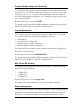
NOTE When the Remote Management feature is enabled on the Remote module, the remote module must either be installed in an unmanaged chassis or in a managed chassis with the SNMP-management disabled (iMediaChassis chassis with the SNMP management module removed). By default this feature is set to Disabled. This feature can only be selected by setting the DIP Switches manually. Loopback Testing The iMcV-DS3/E3/STS includes two loopback test modes: Coax Loopback and Fiber Loopback.
The following illustrations show a typical progression of loopback tests (i.e. starting by checking the coax segment at the local side, then the coax segment at the remote side, etc). Pseudorandom Bit Sequence (PRBS) Testing To test using Pseudorandom Bit Sequence, configure the iMcV-DS3/E3/STS modules for No Loopback, then configure the Transmit Data Source to “Transmit Pseudorandom Bit Sequence.
Installation Troubleshooting General Troubleshooting • During installation, first test the fiber and BNC connections with all troubleshooting features disabled; then enable these features, if desired, just before final installation. This will reduce the features’ interference with testing. • When working with units where the features cannot be disabled, you must establish BOTH your BNC and fiber connections; the NO LNK LEDs should not be lit (i.e.
IMC Networks Technical Support Tel: (949) 465-3000 or (800) 624-1070 (in the U.S. and Canada); +32-16-550880 (Europe) Fax: (949) 465-3020 E-Mail: techsupport@imcnetworks.com Web: www.imcnetworks.com Fiber Optic Cleaning Guidelines Fiber Optic transmitters and receivers are extremely susceptible to contamination by particles of dirt or dust, which can obstruct the optic path and cause performance degradation. Good system performance requires clean optics and connector ferrules. 1.
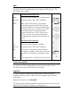
Safety Certifications UL/CUL: Listed to Safety of Information Technology Equipment, including Electrical Business Equipment. CE: The products described herein comply with the Council Directive on Electromagnetic Compatibility (2004/108/EC) and the Council Directive on Electrical Equipment Designed for use within Certain Voltage Limits (2006/95/EC). Conforms to UL Std. 60950-1; Certified to CSA Std. C22.2 No.
19772 Pauling • Foothill Ranch, CA 92610-2611 USA TEL: (949) 465-3000 • FAX: (949) 465-3020 www.imcnetworks.com © 2009 IMC Networks. All rights reserved. The information in this document is subject to change without notice. IMC Networks assumes no responsibility for any errors that may appear in this document. iMcV-DS3/E3/STS Repeater is a trademark of IMC Networks. Other brands or product names may be trademarks and are the property of their respective companies.