iMcV-DS3/E3/STS-LineTerm Operation Manual
FCC Radio Frequency Interference Statement This equipment has been tested and found to comply with the limits for a Class B computing device, pursuant to Part 15 of the FCC Rules. These limits are designed to provide reasonable protection against harmful interference when the equipment is operated in a commercial environment.
Table of Contents FCC Radio Frequency Interference Statement ....................................................ii Warranty............................................................................................................ii About the iMcV-DS3/E3/STS-LineTerm...............................................................1 Configuration .....................................................................................................1 Prerequisites ...............................................
About the iMcV-DS3/E3/STS-LineTerm iMcV-DS3/E3/STS-LineTerm is an SNMP manageable module that converts standard thin coax signals ( DS3, E3/STS, STS ) to a single-mode or multi-mode fiber signal. It performs the standard “LineTermination” (GR-820-CORE) function of these TDMbased line signals. This function transmits an Alarm Indication Signal (AIS) on the line whenever a received signal is lost.
Managed Modules The iMcV-DS3/E3/STS-LineTerm modules can be remotely managed when installed in an iMediaChassis with an SNMP management module. For a managed an environment, first manually configure the desired features through DIP Switch settings to ensure that they continue to function if management is ever lost. After the module is installed, modify the SNMP enabled features by using the iView2 SNMP management software. In a managed chassis, the software settings take priority over DIP Switch settings.
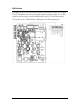
DIP Switches The iMcV-DS3/E3/STS-LineTerm DIP Switches are located at S1 and S2 on the PCB. The S2 DIP Switches are factory configured and must not be changed. The S1 DIP Switches provide control over the available iMcV-DS3/E3/STS-LineTerm features.
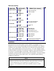
DIP Switch Settings FUNCTION SWITCH SET RESULT [(D) = Default] Loopback (iView2 Configurable) S1-1: OFF Loopback Disabled (D) S1-1: ON Loopback Enabled Loopback Type (iView2 Configurable) S1-2: OFF Coax (D) S1-2: ON Fiber Not Used S1-3: OFF S1-3: ON Fault Loopback (iView2 Configurable) S1-4: OFF Fault loopback Disabled (D) S1-4: ON Fault loopback Enabled Line Build-Out S1-5: OFF 0 to 255 ft. (D) S1-5: ON > 255 ft.
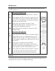
LED Operation The iMcV-DS3/E3/STS-LineTerm module features several diagnostic LEDs per port. The LED functions are: LEDs Next to Coax (BNC) Port ER Flashes yellow whenever a line code violation is received. LOS Glows red when the BNC is receiving no signal and is in an LOS ALARM state, resulting in sending an RAI signal to the fiber port. If Fault Loopback is set to ON, then AIS will also be sent to the Coax line as well. PRBS Glows green when the BNC port receives a valid Pseudorandom Bit Sequence.
Loopback (DIP Switch S1, Position 1) This switch enables or disables the loopback feature. When this feature is enabled, the data line (Coax or Fiber) set by the “Loopback Type” DIP Switch is looped back. By default this feature is DISABLED. This feature can be controlled by SNMP management software (iView2) when the iMcV-DS3/E3/STS-LineTerm module, configured as a HOST, is installed in a managed chassis.
Transmit LIU Waveshape (Line Build-Out) (DIP Switch S1, Position 5) This switch selects the optimal transmit waveshape for the line build-out distance on the coax line. The transmit waveshape can be set for a distance of either 0 to 255 feet or over 255 feet. This feature corrects problems related to cabling (i.e., crosstalk, electromagnetic interference, etc). Improperly setting this switch will cause signal degradation. By default this feature is set to 0 to 255 feet (450 ft maximum).
Remote Management (DIP Switch S1, Position 10) This switch enables or disables the Remote Management mode. Enabling Remote Management on the Remote module allows all SNMP configurable features for the Remote modules to be configured from the Host module. NOTE The Remote Management feature must be enabled on the Remote module. The Remote module cannot be managed by the management chassis it is located in. The local management can read the card settings but cannot make changes to them.
• Copies the incoming signal back out to the origin while continuing to transmit this signal downstream. • Blocks downstream data from arriving on the looped data line. Loopback testing is useful for troubleshooting problems with network connections should they occur. Looping received data back onto the transmit path helps determine whether a connection is still valid.
Pseudorandom Bit Sequence (PRBS) Testing To test using the internal Pseudorandom Bit Sequence source, ensure that the Central Office and the Customer Premises equipment are configured for loopback. The iMcV-DS3/E3/STS-LineTerm modules should be set to normal default mode. On the HOST iMcV-DS3/E3/STS-LineTerm module, set the Transmit Coax Data Source to “Transmit Pseudorandom Sequence" (S1-6, S1-7=OFF).
Installation Troubleshooting General Troubleshooting • The Coax Port can easily be tested using the internal PRBS signal generator and detector and a physical wire loop on the coax interface. • The Fiber Port is internally tested at all times by a working pair of units. With one unit configured for Local Management (Switch 10 set OFF) and the other for Remote Management (Switch 10 set ON), the fiber line is verified if the “RM” LED is ON at both ends of the fiber line.
Specifications Standards Compliance (DS3, E3/STS, STS): ANSI T1.102-1993 ANSI T1.107.1995 GR-820-CORE DS3, E3/STS, STS Interface: BNC coax 75 +/- 5% ohms DS3 (44.736 Mbps +/- 20 ppm) E3/STS (34.368 Mbps +/- 20 ppm) STS (51.840 Mbps +/- 20 ppm) Power Consumption (Typical): 0.550 Amps @ 5 V Operating Temperature: 32° to 122° F (0° to 50° C) Storage Temperature: 0° to 160°F (-20° to 70° C) Humidity: 5 to 95% (non-condensing); 0 to 10,000 ft. altitude Dimensions: 4.19” x .78” x 2.75” (106.4 mm x 19.81 mm x 69.
IMC Networks Technical Support Tel: (949) 465-3000 or (800) 624-1070 (in the U.S. and Canada); +32-16-550880 (Europe) Fax: (949) 465-3020 E-Mail: techsupport@imcnetworks.com Web: www.imcnetworks.
Fiber Optic Cleaning Guidelines Fiber Optic transmitters and receivers are extremely susceptible to contamination by particles of dirt or dust, which can obstruct the optic path and cause performance degradation. Good system performance requires clean optics and connector ferrules. 1. Use fiber patch cords (or connectors, if you terminate your own fiber) only from a reputable supplier; low-quality components can cause many hard-to-diagnose problems in an installation. 2.
Electrostatic Discharge Precautions Electrostatic discharge (ESD) can cause damage to any product, add-in modules or stand alone units, containing electronic components. Always observe the following precautions when installing or handling these kinds of products 1. Do not remove unit from its protective packaging until ready to install. 2. Wear an ESD wrist grounding strap before handling any module or component.
Safety Certifications UL/CUL: Listed to Safety of Information Technology Equipment, including Electrical Business Equipment. CE: The products described herein comply with the Council Directive on Electromagnetic Compatibility (2004/108/EC) and the Council Directive on Electrical Equipment Designed for use within Certain Voltage Limits (2006/95/EC). Conforms to UL Std. 60950-1; Certified to CSA Std. C22.2 No.
19772 Pauling • Foothill Ranch, CA 92610-2611 USA TEL: (949) 465-3000 • FAX: (949) 465-3020 www.imcnetworks.com © 2009 IMC Networks. All rights reserved. The information in this document is subject to change without notice. IMC Networks assumes no responsibility for any errors that may appear in this document. iMcV-DS3/E3/STS-LineTerm is a trademark of IMC Networks. Other brands or product names may be trademarks and are the property of their respective companies.