IE-MiniFiberLinX-II Operation Manual
FCC Radio Frequency Interference Statement This equipment has been tested and found to comply with the limits for a Class A computing device, pursuant to Part 15 of the FCC Rules. These limits are designed to provide reasonable protection against harmful interference when the equipment is operated in a commercial environment.
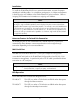
Table of Contents FCC Radio Frequency Interference Statement .....................................................i Warranty.............................................................................................................i About the IE-MiniFiberLinX-II.............................................................................1 iView² Management Software ............................................................................1 Installation ...................................................
About the IE-MiniFiberLinX-II The IE-MiniFiberLinX-II is an optical demarcation network interface device, allowing fiber network operators to connect to and manage remote network segments. Advanced networking capabilities allow operators to easily observe both end points and the fiber link between them as a single management entity, rather than as separate networks.
Network Node Manager. Refer to the iView² help files for information regarding configuring and managing the IE-MiniFiberLinX-II. iView² supports the following platforms: • • • Windows NT Windows 2000 Windows XP iConfig Utility iConfig is an in-band utility created by IMC Networks, used for SNMP configuration for IMC Networks’ SNMP-manageable devices.
Installation To install the IE-MiniFiberLinX-II into a network environment, connect the proper twisted-pair and fiber cables. In a standalone configuration, or if direct management is desired, assign an IP Address to the IE-MiniFiberLinX-II after installation. Refer to Assigning IP Information for information on assigning an IP Address.
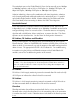
Powering Options The IE-MiniFiberLinX-II powering options include AC and DC power as well as Power over Ethernet, functioning as a PD compliant with 802.3af. The DC Terminal block allows you to daisy-chain one IE-MiniFiberLinX-II to another. To use the DC terminal block, connect to any one positive and any one negative terminal from a power source. The illustration shows the wiring configurations for the DC terminal block (7 to 50 VDC).
The twisted pair port on the IE-MiniFiberLinX-II can also be manually set for 10 Mbps or 100 Mbps operation and for Half- or Full-Duplex (i.e. 10 Mbps Full-Duplex, 10 Mbps Half-Duplex, 100 Mbps Full-Duplex or 100 Mbps Half-Duplex). Selective Advertising, when used in combination with Auto Negotiation, advertises only the configured speed and duplex mode for the twisted pair port.
Using LinkLoss and FiberAlert In a typical central site to remote site media conversion, it is recommended the LinkLoss and FiberAlert features are enabled as indicated in the following: Feature FiberAlert TX LinkLoss FX LinkLoss FiberAlert and LinkLoss Enabled Fault Location Remote Side Only Remote Side (or both) Host Side (or both) Fiber Twisted Pair Fiber Port Affected Fiber Fiber Twisted Pair WARNING Do not enable FiberAlert on both modules when using them in pairs.
Regardless if there is a break in segment 1, 2 or 3, the link will drop on the switches at both ends. The link fault is passed through the media conversion and is observed at each end. It acts just like it would if the devices were directly connected. Loopback Testing The IE-MiniFiberLinX-II includes Loopback testing functionality. During loopback testing, management traffic entering the uplink port is still capable of managing the device.
data, the Loopback feature can also be set to clear the multicast bit. This allows the looped data to avoid being blocked by any multicast settings. Loopback Testing in a Host/Remote configuration The IE-MiniFiberLinX-II is strictly a CPE device; configuration on a Host would require an iMcV-FiberLinX-II; select No Learning on OPTICS and DATA Ports on the Host; on the Remote, choose SRC/DST Address Swap or Address Swap and Clear Multicast Bit.
Configuration The IE-MiniFiberLinX-II includes many features that function automatically or are configurable via iView², iConfig, or a serial/Telnet session. Software Configuration The following table presents port options configurable from iView² or from a serial/Telnet session. Refer to the iView² section later in this chapter or the iView² Help file for more information. For information on configuring VLANs, refer to the Serial Configuration/Telnet Session section in this chapter.
Main Configuration Screen Press Enter, at the prompt, to display the main configuration screen.
Command List I P T K C U E Reboot D Space Bar = = = = = = = = = = Enter New Saved Parameter Values Change Password New Trap Destination Remove ALL Trap Destinations New Community String Delete ALL Community Strings End Session Reboots the IE-MiniFiberLinX-II Enable/disable DHCP Opens the Device Specific Configuration Options Assigning TCP/IP Information To modify the Saved Parameter Values (i.e., assign IP address and subnet mask), press I.
Removing Trap Destinations To remove all trap destinations, press K. Press Y to continue to confirm or N to abort and then, press Enter. To selectively remove community strings, use iConfig to configure the device. Creating Community Strings Community strings add a level of security to a network. The default community string is named “public” and has read/write access.
Rebooting the Unit To reboot the IE-MiniFiberLinX-II, type reboot. Enabling/Disabling DHCP To toggle DHCP on the IE-MiniFiberLinX-II between enable and disable, press D. Additional Device-Specific Commands The IE-MiniFiberLinX-II also includes the following device-specific options. To access these options, perform the following: 1. Press the Space Bar when in the Command List section of the Main Configuration screen (serial configuration/Telnet session). 2.
config accounts sysdescr unit bw sfpstats Allows VLAN and transparency mode configurations. Allows the addition of new users. Allows the editing of sysName, sysDescr, and Port information text. Unit Global Setting Bandwidth Limiting Controls Provides information about the wavelength, serial number, output power, BER, and other useful information. Cleandb Entering cleandb reboots the unit with its database cleaned depending on the option selected.
Viewing Port RMON Statistics To view port RMON (Remote MONitoring) statistics on the IE-MiniFiberLinX-II, enter rmstats. This will display RMON information on packets received as defined in RFC 2819 for RMON. Pressing the Space Bar will refresh the data on the screen. Version Entering version will display the version of the firmware operating the IEMiniFiberLinX-II.
NOTE In the examples shown, ports are referred to as how they appear on the unit itself. Some screens may show TX and FX for the port titles. In this case, TX = DATA port and FX = OPTICS port. Reboot Entering reboot will save settings and reboot the IE-MiniFiberLinX-II. Setting Security Security settings on the IE-MiniFiberLinX-II are reserved for non-standard configurations. Most users won’t utilize this screen.
Advertise FlowC and Force FlowCtrl - This is the FlowControl feature. • • • • When using FlowControl functionality on any port, enable Global FlowControl. Then, configure each port individually. When using Auto Negotiation and FlowControl, set Advertise FlowC to Advertise Flow and set Force FlowCtrl to Flow Auto. Set Advertise FlowC to No Flow to disable FlowControl on a given port.
How to configure the IE-MiniFiberLinX-II for management on the copper port 1. Configure the device to be set in the default mode. If unsure of the device's configuration, perform a cleandb which will set the device to the default setting. This resets the IP address (see page 14 for information on the cleandb function). 2. Make sure that the version of firmware is 722-10b5 or higher. 3. Telnet into the device. Press Enter for device configuration mode.
Press the Space Bar once for access to additional commands. Type config then press Enter to set the operation mode.
Press Enter for other options. Press 2 to change to Default Plus Mode, then press Enter. Press Y to allow TX management, then press Enter.
Press S to save the configuration. Reboot the device and use the SNMP software to manage the device over the copper port. Mode Two - Transparency with Untagged Management This mode is designed to pass all tagged and extra-tagged customer traffic unchanged and must be managed using untagged traffic only. It does not add or remove tags. Select Y on the initial config screen and from the Transparent Mode Setup screen, select N in the fields.
Mode Three - Transparency with Tagged Management This mode will pass all tagged and untagged customer traffic. Management traffic must be tagged. It does not add or remove tags. Select Y on the initial config screen. From the Transparent Mode Setup screen, select Y and enter the Management Tag.
Mode Four - Transparency with Extra Tagging (or Q-in-Q) This mode is designed to either pass all customer traffic with the defined extra tag (Qin-Q) or add and remove the defined extra tag (Q-in-Q) on all customer traffic. Management traffic can be tagged or untagged. Select Y on the initial config screen and then, select Y when asked to select Extra Tags.
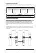
Mode Six - Port VLAN This mode tags all customer traffic received by the copper port going to the fiber port, untagging traffic conversely. This tag is entered as the Data VLAN tag with the optical Tags selected as YES to indicate it is added at the egress of the optical port. Select N on the initial config screen and then setup the VLAN screen. The table below displays how the settings are entered.
Sysdescr offers the options of assigning a system name, System Contact System Location, Unit Description and individual Port names. Enter a description or name, up to 32 characters per line. Press the Enter key to complete the editing task. To change the MIB name of the IE-MiniFiberLinX-II as it appears on the network, type sysname and press Enter. Enter a new name, not exceeding 16 characters in length.
802.1p Base Pri Set the level of 802.1p base priority (3 or 4). The IE-MiniFiberLinX-II has two outgoing queues; one for high priority traffic and one for low priority traffic. If the Base VLAN Priority is 4 for example, 0-3 are low priority and 4-7 are high priority. If the Base VLAN Priority is changed to 3, 0-2 are low priority and 3-7 are high priority. Serial Configuration/Telnet Session Access to the IE-MiniFiberLinX-II can be managed by typing accounts and pressing Enter from the command screen.
Administrator This role can perform Operator role functions, add/delete accounts, and use the cleandb command. Account access through the serial port is at the Administrators level (default). DHCP DHCP Disable (Static IP Addressing) DHCP is disabled in the default configuration. Initially, modules are assigned a Static default IP Address of 10.10.10.10. Changes to the Static IP Address can be added manually through iConfig, an RS-232 Serial session, or Telnet.
A navigation bar on the top of the screen displays the options for configuring the IEMiniFiberLinX-II connection. These options include the following: Host Displays the configuration screen for the Host connection. Remote Displays the configuration screen for the Remote connection. This will show the IE-MiniFiberLinX-II configuration information. Information on this screen is provided on the following page. NOTE The Host and Remote buttons will not appear when configuring the IE-MiniFiberLinX-II alone.
The Configuration/Remote Screen Depending on whether the IE-MiniFiberLinX-II is being set up as a standalone or in a Host/Remote connection, the Configuration or Remote buttons will show a screen for configuring the IE-MiniFiberLinX-II settings. In addition to allowing setting changes on the IE-MiniFiberLinX-II, settings on the ports can also be changed from the Configuration/Remote screen.
configurations, IP Address configuration and SNMP agent settings. The configuration file can be transferred from the unit to a PC and saved to disk through the iConfig protocol. The configuration file can be transferred from a PC to a unit of the same type through iConfig or TFTP into the unit’s Large File Area. After the transfer is complete, the unit copies the configuration to flash and reboots.
Configuration File Basics Saving a Configuration File to Disk: From the Administration Tab in iConfig click the Save Configuration button: The user is prompted for a filename: 31
The user is prompted to enter any notes to the header of the saved file for future reference when uploading the file through iConfig: After the file transfer from the device to disk, the user is notified of the status: 32
Uploading a Saved Configuration File through iConfig From the Administration Tab in iConfig click the Upload Configuration button: The user will be prompted to select a configuration file.
Uploading a Saved Configuration File through TFTP From the commands list in the CLI (Serial or Telnet) run the download command by typing in download: In the download command screen type in the IP Address of the TFTP server and the file name to retrieve. The user will be prompted to continue that retrieval process by pressing the ENTER key or cancel by typing “Q”.
After the transfer process is complete the user will be prompted to press the Enter key again to load the configuration file: Once loaded into the device’s SNMP memory area, the user will be prompted to reboot the device to make the new configuration active: 35
Product Applications The IE-MiniFiberLinX-II comes with a variety of features for different network environments. When used with different types of IMC Products, some features can be enabled, such as extra tagging or “Q-in-Q”, and different network setups come with different requirements. The network setup example below shows one deployment scenario with a full range of management options.
Modes of Operation The following are application examples of Operation Modes for the IE-MiniFiberLinXII. There are six modes of operation that can be configured through the Serial/Telnet session. All modes of operation block management traffic from the user network on the Data port. Mode One - Default The default mode is provided to pass only untagged traffic. Default Plus The Default Mode Plus allows tagged and untagged traffic to pass between the data and optics ports.
Mode Three - Transparency with Tagged Management This mode will pass all tagged and untagged customer traffic. Management traffic must be tagged. It does not add or remove tags. Mode Four - Transparency with Extra Tagging (or Q-in-Q) This mode is designed to either pass all customer traffic with the defined extra tag (Qin-Q) or add and remove the defined extra tag (Q-in-Q) on all customer traffic. Management traffic can be tagged or untagged.
Mode Five - VLAN Filter This mode is designed to only pass traffic with any of the 32 tags that have been identified in the user-defined table. No untagged traffic can pass and management traffic must be tagged. No tags are added or removed from the traffic. NOTE VLAN IDs can be any number between 1 and 4,094. Mode Six - Port VLAN This mode tags all customer traffic received by the copper port going to the fiber port, untagging traffic conversely. Management traffic must be tagged.
Troubleshooting If a fiber connection cannot be established, perform the following to make sure that the fiber transceivers on the IE-MiniFiberLinX-II are not over/under driving the fiber receivers: 1. Make sure the fiber wavelength on both connected devices match (i.e. both are 1310 nm single-mode fiber). 2. Make sure that FiberAlert is enabled on only one unit when connecting an IEMiniFiberLinX-II to another IMC Networks media converter with the FiberAlert feature. 3.
IE-MiniFiberLinX-II Modes of Operations For enlarged version go to IMC Networks website: http://www.imcnetworks.com/Products/12_IE-MiniFiberLinX-II.
The Agent Info Screen Information about the SNMP Agent software managing the IE-MiniFiberLinX-II is contained on this screen. Specifications Input Specifications AC Wall Adapter 100 to 240 ±10% V AC input, 5V DC output DC Input Voltage 1A @ 5V DC to 0.1A @ 50V DC IEEE 802.
Fiber Optic Cleaning Guidelines Fiber Optic transmitters and receivers are extremely susceptible to contamination by particles of dirt or dust, which can obstruct the optic path and cause performance degradation. Good system performance requires clean optics and connector ferrules. 1. Use fiber patch cords (or connectors, if you terminate your own fiber) only from a reputable supplier; low-quality components can cause many hard-to-diagnose problems in an installation. 2.
Safety Certifications UL/CUL: Listed to Safety of Information Technology Equipment, including Electrical Business Equipment. CE: The products described herein comply with the Council Directive on Electromagnetic Compatibility (2004/108/EC) and the Council Directive on Electrical Equipment Designed for use within Certain Voltage Limits (2006/95/EC). Certified to Safety of Information Technology Equipment, Including Electrical Business Equipment. For further details, contact IMC Networks.
19772 Pauling • Foothill Ranch, CA 92610-2611 USA TEL: (949) 465-3000 • FAX: (949) 465-3020 www.imcnetworks.com © 2009 IMC Networks. All rights reserved. The information in this document is subject to change without notice. IMC Networks assumes no responsibility for any errors that may appear in this document. IE-MiniFiberLinX-II is a trademark of IMC Networks. Other brands or product names may be trademarks and are the property of their respective companies.