
Instruction manual


2
Installing IE-iMcV-VDSL2-LANextender Modules
If the VDSL line is connected to the outside plant, the wire entry point to the building
must have primary line protectors installed (Bourns 2377-45 Series DigiGard or
equivalent, illustrated in the Primary Line Protector section).
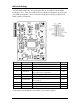
Before installing an IE-iMcV-VDSL2-LANextender module, set the options using the
DIP Switches (refer to the DIP Switch Settings section for more information).
Install IE-iMcV-VDSL2-LANextender modules in any IMC Networks iMediaChassis
series or a MediaChassis series. Each module requires one slot in the chassis; always
use IE-iMcV-VDSL2-LANextender modules in pairs with the Host module at the CO
and the Remote module at the CPE.
To install a module, remove the blank brackets (if present) covering the slots where
you will install the module by removing the screws on the outside edges of the
bracket. Slide the module into the chassis, via the card guides, until the module is
seated securely in the connector. Secure the module to the chassis by tightening the
captive screw. Save any blanks removed during installation for future use.
Remote (CPE) modules can be installed in a managed or unmanaged chassis. Remote
(CPE) modules can only be managed from the connected Host (CO)
IE-iMcV-VDSL2-LANextender module installed in a managed chassis. The user
should always set remote DIP Switches to provide a base value under VDSL line fault
conditions. In addition, some features may not be software configurable on the
remote unit. After setting the DIP Switches, install the IE-iMcV-VDSL2-LANextender
module. Once the VDSL line is established the line can be monitored and
configured through the iView
2
management software available for download at
www.imcnetworks.com
.