
Instruction manual


1
About the IE-iMcV-VDSL2-LANextender
The IE-iMcV-VDSL2-LANextender enables LAN and Campus network managers, and
service providers, to use an existing phone-grade wiring to support high bandwidth
Ethernet connections. Industry standard 2Base-TL provisions symmetric data delivery
over the outside plant defined by IEEE802.3ah. 10Pass-TS transport is designed to
meet short-range, high data rate requirements over standard copper wire defined by
IEEE802.3ah for inside a plant environment. They can achieve this by using Ethernet
over VDSL where the 100m distance limitation of twisted pair data cabling is no
longer a challenge.
Designed with VDSL (second generation Very high-bit-rate Digital Subscriber Line)
technology, the IMC Networks Ethernet-to-VDSL converter allows the transmission of
data over a single pair of sub-standard CAT3 and other telephone cabling to achieve
substantially longer distances. As a media and protocol converter, the IE-iMcV-
VDSL2-LANextender includes the ability to transfer data both symmetrically and
asymmetrically to meet the customer's needs. In either mode, the VDSL2 port
automatically adjusts to an operating point that maximizes the Full-Duplex bandwidth
capability of the line for true plug-and-play operation.
Two IE-iMcV-VDSL2-LANextender media converters are configured as pairs for each
link. One is configured as a Host (Central Office (CO)) IE-iMcV-VDSL2-LANextender
module and is typically deployed at the CO close to network management systems.
The other is configured as a Remote Customer Premise (CPE) IE-iMcV-VDSL2-
LANextender module and is deployed at the CPE. Full CNMP remote line
management is provided through an IMC Networks managed chassis, providing
remote notification of all line fault conditions.
IE-iMcV-VDSL2-LANextender modules include:
•
One VDSL port with an RJ-11 connector (VDSL)
•
One 10/100BaseT Ethernet port with an RJ45 connector (DATA Port)
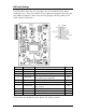
Configuration Instructions
IE-iMcV-VDSL2-LANextender modules include various user-configurable features.
These features are selectable by using DIP Switches and software. The following
sections describe the DIP Switches for the Host (CO) and Remote (CPE) module
configuration.