IE-iMcV-VDSL2-LANextender Operation Manual
FCC Radio Frequency Interference Statement This equipment has been tested and found to comply with the limits for a Class B computing device, pursuant to Part 15 of the FCC Rules. These limits are designed to provide reasonable protection against harmful interference when the equipment is operated in a commercial environment.
Table of Contents FCC Radio Frequency Interference Statement ........................................................... ii Warranty................................................................................................................... ii About the IE-iMcV-VDSL2-LANextender ...................................................................1 Configuration Instructions .........................................................................................
About the IE-iMcV-VDSL2-LANextender The IE-iMcV-VDSL2-LANextender enables LAN and Campus network managers, and service providers, to use an existing phone-grade wiring to support high bandwidth Ethernet connections. Industry standard 2Base-TL provisions symmetric data delivery over the outside plant defined by IEEE802.3ah. 10Pass-TS transport is designed to meet short-range, high data rate requirements over standard copper wire defined by IEEE802.3ah for inside a plant environment.
Installing IE-iMcV-VDSL2-LANextender Modules If the VDSL line is connected to the outside plant, the wire entry point to the building must have primary line protectors installed (Bourns 2377-45 Series DigiGard or equivalent, illustrated in the Primary Line Protector section). Before installing an IE-iMcV-VDSL2-LANextender module, set the options using the DIP Switches (refer to the DIP Switch Settings section for more information).
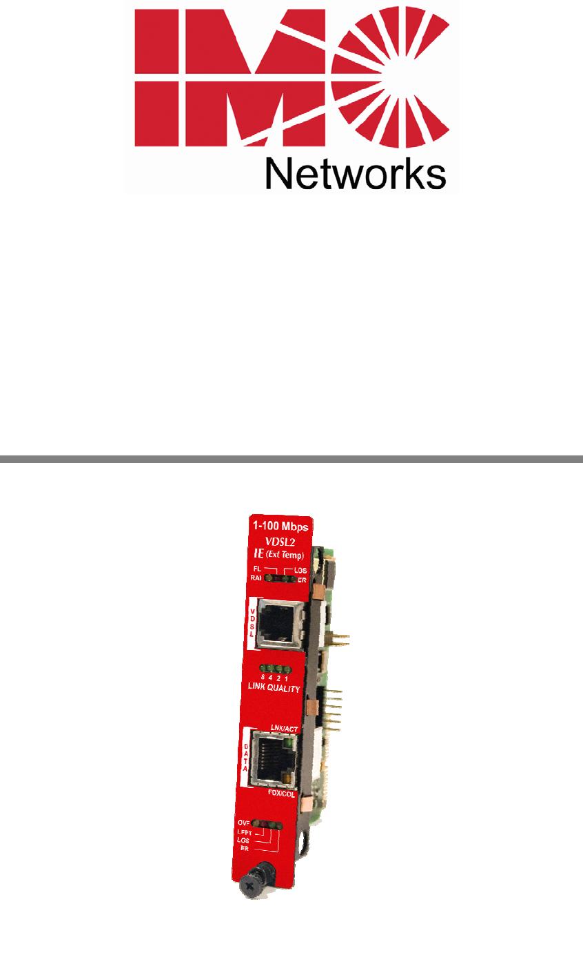
LED Operation LED Function (VDSL) RAI The Remote Alarm Indication led is YELLOW when the unit at the far end of the Unit has an alarm FL Fault Loopback will be ON GREEN if this function is enabled and BLINK if it is actively inhibiting the Ethernet port due to a LOS of the VDSL line LOS ER The LOS led is RED when the VDSL port is down. The ERROR led will Blink YELLOW when the VDSL line receives a symbol error. ON if the VDSL bandwidth falls below the user defined level.
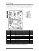
DIP Switch Settings The DIP Switches allow the user to configure most of the module features before installing the unit. These also enable the Host to Remote management channel used with SNMP management. Refer to the following diagram and setting table for DIP Switch selection information.
Host (CO) Module Configuration To allow the HOST (CO) Control Office IE-iMcV-VDSL2-LANextender module to manage the remotely connected CPE IE-iMcV-VDSL2-LANextender unit, set DIP Switch #1 to the OFF position (default setting). This selection can only be performed manually and cannot be overridden by software settings. A Host configured CO IE-iMcV-VDSL2-LANextender module must be installed in a managed chassis to allow SNMP management through iView².
Selective Advertising Selective Advertising (DIP Switch #7) when used in combination with Auto Negotiation, advertises only the configured speed and duplex mode for the DATA port. If Selective Advertising and Auto Negotiation are both switched ON, the DATA port’s speed (10 or 100 Mbps) and Duplex mode (FDX or HDX) are selectively advertised individually per switch setting 5 and 7.
LINK Quality Link Quality is defined by 4 values: 8,4,2,1. The four green LEDs form a binary code indicating the MAX bandwidth the VDSL line can support. The appropriate LED will light once the line quality is dynamically detected. This represents the maximum Downstream data rate (Kbps) the line can support based upon line noise and line length. The Upstream rate will be less based on the Base Plan used.
Overflow activity will be less if Flow Control is enabled. Flow Control or Pause will limit the number of dropped Ethernet frames by reducing the congestion, therefore minimizing the overflow of the VDSL line. Configure the DATA port on IE-iMcV-VDSL2-LANextender module for Flow Control by setting DIP Switch #6 to the ON position.
Maximum Bandwidth IE-iMcV-VDSL2-LANextender Link LEDS The standard single pair IE-iMcV-VDSL2-LANextender unit will provide the following Rate/Reach performance under the best conditions and still maintain a BER > 10^-9 performance over single pair 24 AWG (0.5mm) twisted wire.
The unit will automatically adjust to reach the best bandwidth performance for the physical line it is connected to. The associated LED display will indicate the Bandwidth performance the unit is running at any given time. This is not the bandwidth that is being transmitted but the bandwidth the line is capable of. The Bandwidth number is based on "User Payload" and does not include the Ethernet Frame overhead. For Band Plan 998, this LED display will indicate the MAX down stream rate to the remote unit.
Primary Line Protector NOTE If VDSL line is connected to the outside plant, the wire entry point to the building must have primary line protectors installed.
Appendix—Pinouts RJ-45 Data Port Pinout (MDI) The following table lists the pin configuration for the RJ-45 Data connector. Pin 1 2 3 4 5 6 7 8 Signal Transmit+ TransmitReceive+ No Connection No Connection ReceiveNo Connection No Connection Pin 1 RJ-11 Port Pinout VDSL ports are supported on RJ-11 (pin 3,4) connectors.
Troubleshooting The most common failure of a VDSL line is its slow degradation over time due to aging of the line or increased line noise as additional service is added to the same Line bundle. To help detect this degradation over time, the unit provides a userdefined Minimum Quality Level. Once this level is reached, the unit will send an SNMP TRAP indication for low line quality.
Specifications Standards: ITU-TG.993.1 ITU-TG.997.1 GR-1089-Core Secondary Line Protection Power Consumption (Typical): 550 mA @ 5 V Operating Temperature: -40°F to +185° F (-40°C to +85°C) Storage Temperature: -13° C to 158° F (-25° C to 70° C) Humidity: 5 to 90% (non-condensing); 0 to 10,000 ft.
IMC Networks Technical Support Tel: (949) 465-3000 or (800) 624-1070 (in the U.S. and Canada); +32-16-550880 (Europe) Fax: (949) 465-3020 E-Mail: techsupport@imcnetworks.com Web: www.imcnetworks.
Certifications CE: The products described herein comply with the Council Directive on Electromagnetic Compatibility (2004/108/EC). For further details, contact IMC Networks. Class 1 Laser product, Luokan 1 Laserlaite, Laser Klasse 1, Appareil A’Laser de Classe 1 European Directive 2002/96/EC (WEEE) requires that any equipment that bears this symbol on product or packaging must not be disposed of with unsorted municipal waste.
19772 Pauling • Foothill Ranch, CA 92610-2611 USA TEL: (949) 465-3000 • FAX: (949) 465-3020 www.imcnetworks.com © 2010 IMC Networks. All rights reserved. The information in this document is subject to change without notice. IMC Networks assumes no responsibility for any errors that may appear in this document. IE-iMcV-VDSL2-LANextender is a trademark of IMC Networks. Other brands or product names may be trademarks and are the property of their respective companies.