Giga-AccessEtherLinX-II Operation Manual The above illustration is representative; some minor differences may be present in actual product
FCC Radio Frequency Interference Statement This equipment has been tested and found to comply with the limits for a Class A computing device, pursuant to Part 15 of the FCC Rules. These limits are designed to provide reasonable protection against harmful interference when the equipment is operated in a commercial environment.
Table of Contents FCC Radio Frequency Interference Statement .........................................................i Warranty.................................................................................................................i About the Giga-AccessEtherLinX-II .........................................................................1 Installing the Giga-AccessEtherLinX-II ....................................................................1 Rackmount Installation.............................
About the Giga-AccessEtherLinX-II The Giga-AccessEtherLinX-II Series enables service providers to offer differentiated data networking or VPN services to multi-tenant building and business customers. Residing at the customer premises or at the service provider POP, GigaAccessEtherLinX-II provides a VLAN-based Layer 2 entry point to the MAN fiber network, trunking, differentiating and grooming customer traffic.
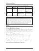
Rackmount Installation The Rackmount kits for the Giga-AccessEtherLinX-II are sold separately: Description 19" Rackmount brackets 19" Rackmount shelf Part Number 895-39226 895-39949 Accessories Includes two brackets that screw onto either side of the GigaAccessEtherLinX-II. Fits into the 19" rack and holds up to 3 units of the GigaAccessEtherLinX-II. Installation The brackets are attached to the unit and then the GigaAccessEtherLinX-II is installed into the rack.
IP-Less Management in HOST/REMOTE configurations A proprietary, secure management communication channel is supported whenever the Giga-AccessEtherLinX-II unit is connected directly to an iMcV-GigaFiberLinX-II unit over the Fiber Uplink. This secure communication channel does not require any pre-configuration or IP address assignment.
About iView² Unit Management iView² is a network management application for IMC Networks’ intelligent networking devices. It features a GUI, which provides network managers the ability to monitor and control IMC Networks’ products. The application is available in several versions including Web-Server version 3.0 and can also function as a snap-in module for HP OpenView Network Node Manager.
SNMP, Telnet and Console Management SNMP, Telnet, and iConfig management channels are always supported through the Giga-AccessEtherLinX-II Uplink Port. This provides a higher level of security so end users cannot access management, alter settings, etc. Management through other ports can be supported through unit configuration. In order for the Giga-AccessEtherLinX-II to support SNMP management, the unit must be assigned IP configuration information (e.g., IP address, subnet mask, etc.
Main Configuration Screen After running through an initial self test, the screen will display: Press Enter for Device Configuration. Press Enter to be taken to the main configuration screen. The Main Configuration screen contains the following: Saved Values — displays changes made during current session. • • • IP Address (Should be assigned during initial configuration) Subnet Mask (Should be assigned during initial configuration) Default Gateway Current Values — displays values currently in use.
NOTE Reboot after making any modifications to the Saved Values or the changes will not take effect. To reboot, type Reboot at the prompt on the main configuration screen, or turn the chassis power OFF, then ON again. Because a Delete key is not available on VT-100 terminal emulators, use the F2 key instead. I Assigning IP Information To modify the Saved Parameter Values (i.e., assign IP address and subnet mask), press I.
default public string. To create a new community string, go to the main configuration screen and press C. Enter the name of the new community (up to 16 characters, no spaces) and press Enter. Then type one of the following to assign the community string’s access rights: R = read-only access W = read/write access Enter = abort Press Enter. When finished, press Enter and then type Reboot for changes to take effect. The Saved Values and Current Values should now both display the changes made (e.g.
E Ending a Session Be sure to press E before disconnecting the cable in order to stop the continuous stream of data to the console port. Space Bar Device-Specific Configuration Options The Giga-AccessEtherLinX-II also includes several device-specific options. To access these options, press the Spacebar from the Command List section of the Main Configuration screen, type the name of the action you want to perform (as shown below) and press Enter.
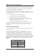
cleandb Reboots the Giga-AccessEtherLinX-II with a clean database. This removes all of the information in the database with an option to change the IP address of device. download Opens the Download dialog from which you download firmware in the Main Configuration screen using TFTP protocol. Displays the Giga-AccessEtherLinX-II serial number and build date. Displays and changes VLAN settings (see Configuring VLANs) Reboots the unit Allows addition/deletion of Username/Password accounts.
*A reboot may be required for some configuration changes to take effect. Downloading Files Firmware and configuration files for the Giga-AccessEtherLinX-II can be downloaded from a central server via TFTP protocol. Initiate this download via console configuration or Telnet session. To download a file, type download and press Enter to be taken to the Download a file screen. This screen displays the IP Address of the TFTP server and the name of the file to be downloaded. The TFTP server should be open.
connection between ports includes management. Management can be assigned a VLAN. Mode 5 Only accepts untagged traffic at the Downlink Ports. All Uplink traffic is tagged. Each Downlink Port adds a Qualified or Not Qualified VLAN tag to all ingress traffic. Management only accepted from Uplink Port and can be assigned a VLAN. Mode 6 Accepts both tagged and untagged traffic at the Downlink Ports. All Uplink traffic is tagged.
Mode 1—Untagged Frames Only In this mode, the unit functions as a managed MAC layer switch with management only accepted on the fiber Uplink and no VLAN support. Mode 2—Mixed Tagged and Untagged Frames (Default) When Management can be VLAN tagged, the following screen is given for configuration.
Mode 3— Mixed Tagged and Untagged, Block MGMT Domain 14
Mode 4— Port Based Forwarding Port Based Forwarding selection is done on the following screen: Mode 5—Port Based VLANs Only untagged frames are delivered to the Downlinks.
Each port can assign two different VLANs based on the ingress frame classification. For untagged frames, the DiffServ priority value of the IP frame can be used for classification. This screen allows the user to select any of the 64 values. In addition the user must identify whether non-IP frames are also classified.
Mode 6—Port Based Extra Tag In this mode both untagged and tagged frames can enter the drop ports. Two VLANs per port can be assigned based on ingress frames classification.
In this mode both tagged and untagged frames can enter the drop port. Tagged frames can now be classified based on the PRI value within the incoming VLAN tag. Any PRI value can be used to classify the frame.
Mode 7— Port Based Extra Tag, Infrastructure 19
Mode 7 allows the user to define whether a port is a Trunk (passes everything, including management), or a Drop (can add/remove VLAN tags). Unit management is also enabled through any Trunk port. Once a port is defined as a Drop Port, additional screens are provided to assign VLAN values based on the classification of the incoming frame.
Mode 7 also allows the user to define whether PRI or DiffServ values are used to classify incoming frames and whether non-IP frames are classified. Classification is done on a port-by-port basis.
Mode 8—VLAN Assigned Mode 8 allows up to 64 VLAN IDs to be defined. Each port can be a tags or No-tags member of a defined VLAN. A tags member port will allow these tagged frames to enter/exit the port. A No-tags member port will add this frame at egress. Only one No-tag VLAN can be assigned to a given port, but any or all defined tags can be assigned as tags for a given port.
Only one No-tags can be assigned to a port; this indicates that all frames entering the port that do not match the assigned members VLAN-ID list are given this indicated tag. All frames leaving the port with this tag will have it removed. Assigned tag frames (tags) will pass through this port without changes. Unit Control Settings Global unit settings are configured on this screen and apply to all ports. Unit Loopback loops all frames entering the fiber Uplink Port back to the fiber port.
Bandwidth Limiting Bandwidth Limiting can be set per port in both transmit and receive directions. The limiting function provides a Leaky Bucket traffic shaping function when placed on the TX side of a port. When the transmit limit is reached on a port, it will stop transmitting until the bucket level falls below the set level. When placed on the RX side it functions more like a hard Bandwidth limiter.
Port Configuration The Giga-AccessEtherLinX-II Downlink Ports can be configured via console configuration. Type ports and press Enter to be taken to the Port Configuration screen. From this screen, users can enable/disable ports and set Auto Negotiation and Flow Control functions, etc. (This can also be performed via iView².) When a port is disabled, it will no longer show LINK or send any traffic to the port. Flow Control will cause a port to send PAUSE whenever the ports internal buffer space is low.
System Descriptions This screen allows the user to define unit and port names that are incorporated by the unit into all SNMP traps. These are extremely useful in troubleshooting the system. Firmware and Unit Version Information To help maintain Software revision control, these reference numbers are always updated whenever unit software is downloaded to the equipment.
Using Management iView² is a network management application for IMC Networks intelligent networking devices. It features a GUI and gives network managers the ability to monitor and control products from a variety of platforms. Using iView² with HP OpenView During the installation, the iView² application will ask if HP OpenView is installed on the management PC. Click Yes to integrate the appropriate files.
IP address assigned to the chassis management card. Users may still assign IP addresses to each iMcV-Giga-FiberLinX-II and Giga-AccessEtherLinX-II, and manage them independently over the network being transported but this may not provide the same level of security as the UMA system. With the Unified Management Agent When an SNMP request for an iMcV-Giga-FiberLinX-II comes in, the SNMP Management Module in the iMediaChassis passes the request to the SNMP agent in the specific module.
Using Telnet Assign the Giga-AccessEtherLinX-II an IP Address or use the default IP Address 10.10.10.10, subnet mask 255.0.0.0 before using a Telnet session. All configurations done via the console port can also be performed using Telnet. The user should only open one Telnet or RS232 console session at a time. Do not use an RS232 console session and a Telnet session at the same time as unexpected results may occur. LED Operation Downlink Ports LNK/ACT Glows green when link is established on port.
Uplink Ports FLT Glows yellow when a fault is detected with the fiber Uplink. Faults include loss of link and half-duplex operation. Half-duplex is not defined for a fiber line running at gigabit rates. Glows green when link is established. Blinks green during data activity. LNK Passwords If the username and password are available when accessing iView², the unit can be reset back to its original factory setting with the following procedure.
Strongly recommended: • • • 128 MB RAM Pentium III 650Mhz or Faster 17” Monitor @ 1024 x 768 Resolution or higher Installing and Using iView² iView² is available to install as a download at www.imcnetworks.com/Products/iView.cfm. When using iView² with HP OpenView During the installation, the iView² application will ask if HP Open View is installed on the management PC. Click Yes to integrate the appropriate files. Once in OpenView, select IMC Networks from the toolbar to view the IMC Networks devices.
This equipment is designed to permit the connection of the grounded conductor of the DC supply circuit to the grounded conductor at the equipment. If this connection is made, all of the following conditions must be met: 1. This equipment shall be connected directly to the DC supply system grounded electrode conductor or to a bonding jumper from a grounded terminal bar or bus to which the DC supply system grounding electrode conductor is connected. 2.
DC Power Supply Precautions The following precautions must be observed when installing the chassis model with an internal DC power supply. 1. 2. Check nameplate ratings to ensure there is no overloading of supply circuits that could affect over current protection and supply wiring. In addition, the following must be observed: a. Connect the equipment to a 36 to 56.7 V DC power source that is electrically isolated from the alternating current source.
Specifications Standards IEEE 802.3x Ethernet IEEE 802.3u Auto Negotiation IEEE 802.1q VLAN IEEE 802.1p Packet Prioritization Operating Temperature +32° F to +122° F (0° C to +50° C) Storage Temperature -40° F to 185° F (-40°C to 85° C) Humidity 10 to 95% (non-condensing) Maximum heat generated 81 BTU/hr Power Requirements (typical) 100-240V AC, 50/60Hz, 0.5/0.25A for AC 48V DC, 0.5A for DC Throughput Up to full wire speed on all ports. Up to 9600 MTU Dimensions Height = 1.64” x Width = 5.64” x Depth = 8.
Fiber Optic Cleaning Guidelines Fiber Optic transmitters and receivers are extremely susceptible to contamination by particles of dirt or dust, which can obstruct the optic path and cause performance degradation. Good system performance requires clean optics and connector ferrules. 1. Use fiber patch cords (or connectors, if you terminate your own fiber) only from a reputable supplier; low-quality components can cause many hard-to-diagnose problems in an installation. 2.
Safety Certifications UL/CUL: Listed to Safety of Information Technology Equipment, including Electrical Business Equipment. CE: The products described herein comply with the Council Directive on Electromagnetic Compatibility (2004/108/EC) and the Council Directive on Electrical Equipment Designed for use within Certain Voltage Limits 2006/95/EC). Certified to Safety of Information Technology Equipment, Including Electrical Business Equipment. For further details, contact IMC Networks. .
19772 Pauling y Foothill Ranch, CA 92610-2611 USA TEL: (949) 465-3000 y FAX: (949) 465-3020 www.imcnetworks.com © 2011 IMC Networks. All rights reserved. The information in this document is subject to change without notice. IMC Networks assumes no responsibility for any errors that may appear in this document. Giga-AccessEtherLinX-II is a trademark of IMC Networks. Other brands or product names may be trademarks and are the property of their respective companies.