Access Converter/3 Operation Manual
FCC RADIO FREQUENCY INTERFERENCE STATEMENT This equipment has been tested and found to comply with the limits for a Class B computing device, pursuant to Part 15 of the FCC Rules. These limits are designed to provide reasonable protection against harmful interference when the equipment is operated in a commercial environment.
TABLE OF CONTENTS FCC Radio Frequency Interference Statement ....................................................ii Warranty............................................................................................................ii About the Access Converter/3 ............................................................................4 Installing the Access Converter/3 ........................................................................5 LED Operation.................................................
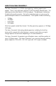
ABOUT THE ACCESS CONVERTER/3 The Access Converter/3 is a 10/100 auto-negotiating, switching, optical access product. There is one uplink port and three 10/100 twisted pair downlink ports. The uplink port can be either fiber or 10/100 twisted pair. The uplink port is located on the back of the media converter. Each of the twisted pair ports can auto-sense the speed and duplex mode of a connected device.
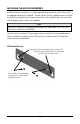
INSTALLING THE ACCESS CONVERTER/3 Install the Access Converter/3 as a table-top device, or mount to a wall surface with the appropriate bracket (included). To wall mount, use the supplied screws to attach the wall-mount bracket to the Access Converter/3, then simply mount the unit to the wall by tightening the screws (not supplied). Note The Access Converter/3 packaging also includes four small rubber “feet” for use in table-top or wall-mount installations.
LED OPERATION Each Access Converter/3 includes diagnostic LEDs for troubleshooting. Fiber Uplink LED TX Downlink LED Front Back Uplink LED Twisted Pair Downlink Ports The LED indicator for the twisted pair downlink port is located on the RJ-45 connector of the downlink port next to the power connector. There are two LED functions for the twisted pair downlink ports.
Fiber Uplink Port The LED indicator for the fiber uplink port is located on the RJ-45 connector of the downlink port next to the power connector. There are four LED functions for the fiber uplink port. The fiber uplink port LED functions are as follows: • Glows green when a link is established on the fiber port. • Glows green indicating a valid link, then blinks green when activity is detected on the fiber port. • When the LED is OFF, there is no link (check cabling, check remote device).
SPECIFICATIONS DC Input Voltage: AC Adapter Input Load: 100/240 ±10% VAC, 0.25A, 50/60 Hz, 5 VDC output with maximum output current of 1A Unit Power Consumption (Typical): 600 mA @ 5 VDC Operating Temperature: 32° to 122° F (0° to 50° C) Storage Temperature: -4° to 158° F (-20° to 70° C) Humidity: 5 to 90% (non-condensing); 0 to 10,000 ft. altitude Dimensions: H=0.92” W=3.50” D=4.00” (2.3 x 8.9 x 10.
SAFETY CERTIFICATIONS UL/CUL: Listed to Safety of Information Technology Equipment, including Electrical Business Equipment. CE: The products described herein comply with the Council Directive on Electromagnetic Compatibility (89/336/EEC) and the Council Directive on Electrical Equipment Designed for use within Certain Voltage Limits (73/23/EEC). Certified to Safety of Information Technology Equipment, Including Electrical Business Equipment. For further details, contact IMC Networks.
19772 Pauling • Foothill Ranch, CA 92610-2611 USA TEL: (949) 465-3000 • FAX: (949) 465-3020 www.imcnetworks.com © 2007 IMC Networks. All rights reserved. The information in this document is subject to change without notice. IMC Networks assumes no responsibility for any errors that may appear in this document. Access Converter/3 is a trademark of IMC Networks. Other brands or product names may be trademarks and are the property of their respective companies.