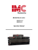
iMediaChassis series iMediaChassis/20 iMediaChassis/6 iMediaChassis/3 Operation Manual
FCC Radio Frequency Interference Statement This equipment has been tested and found to comply with the limits for a Class B computing device, pursuant to Part 15 of the FCC Rules. These limits are designed to provide reasonable protection against harmful interference when the equipment is operated in a commercial environment.
Table of Contents FCC Radio Frequency Interference Statement ........................................................ ii Warranty................................................................................................................ ii About the iMediaChassis/20 ...................................................................................1 iMediaChassis/20 Features ....................................................................................
About the iMediaChassis/3 ...................................................................................16 iMediaChassis/3 Features ....................................................................................16 Alarm Reset, Last Gasp, and Temperature Gauge ............................................16 Alarm Reset Switch .........................................................................................16 Last Gasp Alarm ....................................................................
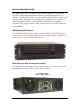
About the iMediaChassis/20 The iMediaChassis series is a modular chassis platform designed for use with IMC Networks’ Simple Network Management Protocol (SNMP) manageable series of modules. The iMediaChassis/20 is a 3U high, Rackmountable chassis that features 20 slots for installing application series modules plus an additional slot for installing an SNMP Management Module. Some iMediaChassis/20 models are capable of redundant power supply modules.
Reset Alarm Switch When one power supply module malfunctions, an audible alarm sounds indicating the loss of the power module. The alarm can be silenced by pressing the Reset Alarm switch, located next to the power connector on the power supply module. If this occurs, remove and replace the power supply module immediately. (LEDs on the Management Module and the power supply module itself also indicate power supply module failures.
The SNMP Management Module can be removed and replaced as necessary. Refer to the SNMP Management Module manual for complete instructions about how to configure and operate. If an SNMP Management Module is installed, refer to the LED panel below for indicators of Link, Temperature, Power supply modules and other functions. SNMP Management Module LEDs The SNMP Management Module features several LEDs. The LED functions are: LNK/ACT Glows green when a link is established on port.
Installing the iMediaChassis/20 Install the chassis first before installing any modules into an iMediaChassis. When installing the chassis, be sure to observe the following precautions to prevent electrical or mechanical damage: 1. Stay within the chassis’ power rating to prevent overload of supply circuits or damage to any overcurrent protection and supply wiring. 2. Maintain a reliable ground, especially when connecting to a power strip instead of directly to a branch circuit. 3.
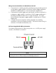
Wiring Instruction Guidelines for iMediaChassis/20-2DC 1. Connection of a suitable grounding conductor to the grounding terminal at each power supply module (a minimum 14AWG copper conductor should be suitable based on a 15A circuit breaker requirement). 2. Connection of suitable supply wiring to the plus and minus terminals at each power supply module (a minimum 14AWG copper conductors is considered suitable based on the 11A input maximum).
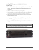
Installing SNMP Management and Application Modules To install a module: 1. Remove the blank bracket (if present) covering the slot where the module will be installed. IMC Networks recommends installing blank brackets in unused module slots. 2. Slide the module into the chassis using the card guides. 3. Secure the module to the chassis by tightening the captive screw. (Refer to the documentation shipped with the module for configuration information.) 4.
Replacing Power Supply Modules User-Replaceable Power Supply Modules While power supply modules are redundant, failed power supply modules should promptly be replaced to maintain network integrity and prevent data loss. To replace a power supply module: 1. 2. 3. 4. 5. Disconnect the power source from the power supply module. Remove the screws of the retainer plate (on some AC modules). Move the Power Supply Release switch toward the right or unscrew captive release screw.
Dual DC, Part Number 850-10954-2DC Dual AC, Part Number 850-10956-2AC NOTE Do not mix AC and DC power supply modules.
iMediaChassis/20 Specifications Input Specifications Dual AC Input: 100 to 240V±10%, 47-63Hz, 6.3A Dual AC Dual DC Input: -38 to -72V DC 11A max (per module) Operating Temperature: 0° C to 50° C (32° F to 122° F) Storage Temperature Dual AC: -20° C to 80° C (-4° F to 176° F) Dual DC: -20° C to 60° C (-4° F to 140° F) Humidity: Dual AC & DC: 20 to 90% (non-condensing at 40° C) Shipping Weight Dual AC: 30 lbs (13.6 kg) Dual DC: 29 lbs (13.15 kg) Dimensions: 5.2" x 19.0" x 13.8" (13.21cm x 48.26cm x 35.
About the iMediaChassis/6 The iMediaChassis series is a modular chassis platform designed for use with IMC Networks’ Simple Network Management Protocol (SNMP) manageable series of modules. The iMediaChassis/6 is 1U high, Rackmountable, capable of offering redundant power supply modules, as well as an SNMP Management Module. iMediaChassis/6 Features The iMediaChassis/6 series offers a line of models including single AC, single DC and dual AC.
• Both power supply modules malfunction • Both power supply modules are powered down • When the AC line fails SNMP Write Lock There is an SNMP Write Lock switch located above the SNMP module slot on the front of the iMediaChassis/6. The SNMP Write Lock switch prevents a new management board from re-configuring the application module settings (e.g., the status of features such as LinkLoss, FiberAlert, Force mode, etc.) made via SNMP on any previous Management Modules.
Installing the iMediaChassis 6 Install the chassis first before installing any modules into an iMediaChassis. When installing the chassis, be sure to observe the following precautions to prevent electrical or mechanical damage: 1. Stay within the chassis’ power rating to prevent overload of supply circuits or damage to any overcurrent protection and supply wiring. 2. Maintain reliable ground, especially when connecting to a power strip instead of directly to a branch circuit. 3.
SNMP Management Modules include two twisted pair ports, one for management and one reserved for future use. The Management Module also features a DB-9 serial port, and supports SNMP V1/V2c. Installing Management and Application Modules Installing Applications Modules To install a module: 1. Remove the blank bracket (if present) covering the slot where the module will be installed. IMC Networks recommends installing blank brackets in unused module slots. 2.
DC Power Wiring, Replacing Power Supply Modules and Fans DC Power Supply Wiring Instructions The following diagram shows the wiring configurations for -48 VDC power supply modules for the iMediaChassis/6. User-Replaceable Power Supply Modules The iMediaChassis/6 ships from IMC Networks with one or two power supply modules installed depending on the model. Chassis ordered with one power supply come with a filler tray installed in the second slot. To install a second power supply: 1. 2. 3.
iMediaChassis/6 Specifications Input Specifications Dual AC Input: 100/240VAC 47-63Hz 1.8A @10VAC 115V @ 1.6A and 230V @ 0.8A (single) Dual DC Input: 48VDC, 3.3A Operating Temperature: AC: -25° C to 50° C (-130° F - 122° F) DC: -40° C to 100° C (-40° F - 212° F) Storage Temperature: AC: -40° C to 85° C (-40° F - 185° F) DC: -55° C to 125° C (-67° F - 257° F) Humidity: 5 - 90% (non-condensing); 0-10,000 ft. altitude Shipping Weight: 13 lbs (5.90 kg) Dimensions: 1.75” x 17.35” x 10.65” (4.45cm x 44.07cm x 27.
About the iMediaChassis/3 The iMediaChassis series is a modular chassis platform designed for use with IMC Networks’ Simple Network Management Protocol (SNMP) manageable series of modules. The iMediaChassis/3 is a 1U high, a Rackmountable, capable of offering redundant power supply modules, as well as an SNMP Management Module. iMediaChassis/3 Features The iMediaChassis/3 series offers a line of models including single AC, single DC, dual AC and dual DC.
Installing the iMediaChassis/3 Install the chassis first before installing any modules into an iMediaChassis. When installing the chassis, be sure to observe the following precautions to prevent electrical or mechanical damage: 1. Stay within the chassis’ power rating to prevent overload of supply circuits or damage to any overcurrent protection and supply wiring. 2. Maintain reliable ground, especially when connecting to a power strip instead of directly to a branch circuit. 3.
SNMP Write Lock The SNMP Write Lock switch is located on the back of the iMediaChassis/3. The SNMP Write Lock switch prevents a new management board from re-configuring the application module settings (e.g., the status of features such as LinkLoss, FiberAlert, Force mode, etc.) made via SNMP on any previous Management Modules. NOTE Leave this switch in the NORMAL position during day-to-day operation; the LOCKED position should only be used when changing the SNMP management board.
SNMP Management Module LEDs The SNMP Management Module features several LEDs. The LED functions are: LNK/ACT Glows green when a link is established on port. Blinks green when data activity occurs. FDX/COL Glows yellow when port is in Full-Duplex mode. Blinks yellow when port is operating in HalfDuplex mode and collisions occur. TEMP Glows yellow when temperature of unit surpasses a user-defined level. PS Glows yellow when one power supply module malfunctions.
Power Supply Modules Power supply modules in all models of the iMediaChassis/3 are fixed, and not enduser replaceable. Fans The iMediaChassis/3 includes temperature-triggered fans. When the temperature of the chassis reaches 40° C, the two fans activate to cool the chassis. The fans operation can be tested by holding the Reset Alarm Switch down for 4 to 5 seconds. The fans will activate and then they will turn off when the button is released. If the fans do not activate, contact IMC Networks.
Hardware Feature Matrix Power Supply iMediaChassis/20 iMediaChassis/6 iMediaChassis/3 AC, 2AC, 2DC AC, 2AC, DC, 2DC AC, 2AC, DC, 2DC Modular Modular Fixed End user replaceable No Yes No LEDs Yes Yes Yes Redundant upgrade on single slot chassis No Yes No Versions Type *Trap can be set for exceeding a temperature value ** Active only when triggered by temperature reaching 40° C 21
IMC Networks Technical Support Tel: (949) 465-3000 or (800) 624-1070 (in the U.S. and Canada); +32-16-550880 (Europe) Fax: (949) 465-3020 E-Mail: techsupport@imcnetworks.com Web: www.imcnetworks.com Electrostatic Discharge Precautions Electrostatic discharge (ESD) can cause damage to your add-in modules. Always observe the following precautions when installing or handling an add-in module or any board assembly. 1. Do not remove unit from its protective packaging until you’re ready to install it. 2.
Safety Certifications UL/CUL: Listed to Safety of Information Technology Equipment, including Electrical Business Equipment.
19772 Pauling • Foothill Ranch, CA 92610-2611 USA TEL: (949) 465-3000 • FAX: (949) 465-3020 www.imcnetworks.com © 2008 IMCNetworks. All rights reserved. The information in this document is subject to change without notice. IMC Networks assumes no responsibility for any errors that may appear in this document. iMediaChassis series is a trademark of IMC Networks. Other brands or product names may be trademarks and are the property of their respective companies.