
User's Guide
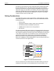
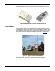
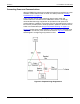
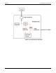
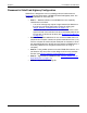
Table Of Contents
- Table of Contents
- Preface
- Chapter 1: Introduction
- Chapter 2: Pre-Installation Considerations
- Chapter 3: Sensor Installation & Setup
- Chapter 4: Operations and Adjustments

Chapter 2: Pre-Installation Considerations
RTMS Echo User Guide ©2019 Image Sensing Systems Inc. 2-5
Connecting Power and Communications
After the RTMS Echo has been mounted to the pole the connections for power
and data communications must be made. For cable pinouts see “Cabling
Considerations” on page 2-2.
A 50 ft (15.24m) Cat 5e cable containing wires for both power and
communications is included with the RTMS Echo sensor. It is strongly
recommended that surge suppression be provided for both power and
communications. In addition, if the power source in the breakout box is solar or
if the source provides power to other equipment in addition to the Echo sensor,
a filter is recommended (see “Surge Suppression/Filtering” on page 2-4
).
Figure 2-5
below shows a block diagram of the connections if separate surge
suppressors are used for power and communications. Figure 2-6
shows the
same diagram if a single surge suppressor is used.
Figure 2-5: Separate Surge Suppressors