
User's Guide
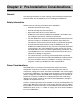
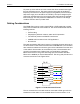
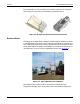
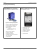
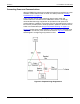
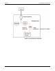
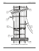
Table Of Contents
- Table of Contents
- Preface
- Chapter 1: Introduction
- Chapter 2: Pre-Installation Considerations
- Chapter 3: Sensor Installation & Setup
- Chapter 4: Operations and Adjustments

Chapter 2: Pre-Installation Considerations
RTMS Echo User Guide ©2019 Image Sensing Systems Inc. 2-3
terminated with an RJ-45 connector, the connector must have an element to
which the ground wire can be connected (see examples below).
Figure 2-2: Example RJ-45 External Ground Connectors
Breakout Boxes
The design of an RTMS Echo installation should include a breakout box close
to the RTMS Echo that can be used for setup and maintenance purposes, and
can include surge suppression circuitry and external communications devices
as required. Reference designs are available. The breakout box should be no
more than 50 ft (15.24 m) from the RTMS Echo sensor (see Figure 2-3
).
Figure 2-3: Typical Breakout Box Installation
Each breakout box should contain a manufacturers approved surge
suppression package, filters, power supply and communications equipment.