EN PRO-LINE GAS COOKTOP & ELECTRIC OVEN FREESTANDING COOKERS OPERATING & INSTALLATION MANUAL cod.
Congratulations, you are now the proud owner of an ILVE cooking appliance. Thank you for purchasing ILVE and welcome to the exciting world of cooking the ILVE way. This instruction manual has been specially created to inform you of the full range of features your ILVE appliance has to offer and serves as an introduction to the wonderful benefits of ILVE’s dynamic cooking systems. We present detailed information on each of the advanced cooking systems built into ILVE appliances.
OPEN 24/7 ILVE ACCESSORIES ONLINE SHOP For a wide range of Genuine ILVE accessories at the click of a button shop.ilve.com.
iWarranty REGISTER YOUR WARRANTY ONLINE NOW GO TO: https://support.eurolinx.com.au/#/form/warrantyregistration As a part of our continued customer service offering, you can now register your ILVE products online at https://support.eurolinx.com.au/#/form/warrantyregistration Just follow our simple online registration process. Please ensure that you always keep your proof of purchase in order for your warranty to remain valid should you ever need to use it.
USER GUIDE CONTENTS INSTALLATION USER GUIDE 32 INFORMATION - To be reminded to the user 4 IMPORTANT SAFETY WARNINGS 14 First operation of the oven 33 INSTALLATION 15 INSTRUCTIONS FOR USE 33 Installation of the cooker 15 Using the hob 33 Room ventilation 17 Use of a steak grill 34 Positioning of the appliance between furniture 18 Proper use of burners 35 How to install the fixing bracket 19 Use of the gas fry-top 36 ELECTRICAL CONNECTIONS 20 Electric Multifunction Oven 36 Groups of cooking
IMPORTANT SAFETY WARNINGS Appliance data As well as being shown on the packaging, the data plate is applied to the oven door frame and is visible with the door open. CAUTION These warnings refer to different types of appliances. Pay attention in properly identifying the type you own (see the data plate). These warnings are valid for the countries mentioned in the plate. 1 Before using the cooker, read the instructions booklet carefully.
USER GUIDE IMPORTANT SAFETY WARNINGS CAUTION continued... 5 When using a gas appliance, heat and dampness are generated inside the premise. A good aeration of the kitchen must be guaranteed by keeping the natural aeration vents open or by installing a mechanical aeration device (hood). An intensive and prolonged utilization of the appliance may result in the need of supplementary aeration, such as opening a window or increasing the power of the hood (if present).
IMPORTANT SAFETY WARNINGS 12 The use of any electrical appliances requires that a number of fundamental rules must be respected: A. Never touch the appliance when you have wet or damp hands or feet; B. Never use the appliance barefoot; C. Avoid using extensions; D. Never pull the electric cable to remove it from the power socket; E. Do not expose the appliance to atmospheric agents(rain, sun, etc...); F. Be careful: accessible parts can become very hot during the use.
USER GUIDE IMPORTANT SAFETY WARNINGS 15 Before cleaning the appliance or carrying out maintenance, disconnect the power supply by removing the plug from the socket or switching off the switch. 16 In case of breakdown or malfunction switch off the appliance and do not attempt any repairs that must only be performed by an authorized service center. Always request original parts. Failure to comply with these instructions may compromise the appliance’s safety.
IMPORTANT SAFETY WARNINGS 23 If the rotation of the gas knobs is difficult, don’t do anything. Close off the gas and call the After Sales Service for advice. 24 Do not use a steam cleaner to clean the inside parts of the oven. 25 Don’t use any abrasive detergent or sharp device to clean the oven glass door. This may cause damage or breakage. 26 Don’t modify the appliance. 27 Be careful: fat spillage, objects or oils on the appliance may cause a fire.
USER GUIDE IMPORTANT SAFETY WARNINGS 35 Do not leave the cooker unguarded during any cooking that can spit fats or oils. 36 Do not touch the heating elements while the appliance is on. Let it cool down before cleaning 37 Food preparation in plastic or aluminum containers on hot cooking zones is forbidden just like the positioning on the cooking surfaces of plastic or aluminum foil objects. 38 Do not cover the burners or the hob with tinfoil.
IMPORTANT SAFETY WARNINGS First system startup of the oven When using the oven for the first time, let it work empty for about 1 hour (230°C), possibly leaving the kitchen windows open. When you first turn the oven on, a bad smell is emitted due to production residues such as grease, oils or resins. When the oven has cooled clean it following the instructions in the «Cleaning and care section». After the indicated time the oven is ready to perform its first cooking.
USER GUIDE IMPORTANT SAFETY WARNINGS BE CAREFUL: keep children and disabled people away during the operation. Do not use the appliance as a heating source. General notes to keep the appliance efficient and safe, maintenance must be entrusted to specialised technicians or to the after-sales service staff. Choose covered pans based on the quantity of food to cook. IMPORTANT Position the flame divider “b” correctly.
INSTRUCTIONS FOR USE - First system startup of the hob Recommended pans according to burner size: Burners ID Meduim SR 10 ÷ 20 Large R 20 ÷ 24 Fish buner P Ring Dual - Ring Operating the DUAL WOK Symbol ● ● ● Diameter Ø (cm) oval pans (380 x 185) TC/DCC 22 ÷ 28 DUAL 24 ÷ 30 Identify the knob with the help of the index near the knobs. Press and turn the knob to the symbol (maximum) for 5 seconds.
USER GUIDE INSTRUCTIONS FOR USE – Use of a grill pan Grill pan If you want to use a grill pan a few things must be taken into account: - to preheat the grid on the burner’s maximum power for no more than 10 minutes; - we recommend cooking foods with reduced power; - keep at least a distance of 150mm from the side wall to the gridiron’s rim; - do not position the grill pan on more than one burner at the same time.
INSTRUCTIONS FOR USE – Positioning placement of the burners Positioning of the burners BURNERS BE CAREFUL: always check that the burners are properly positioned), with a uniform flame that is not noisy.
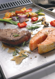
USER GUIDE INSTRUCTIONS FOR USE – Use of the gas fry-top (on applicable models) FRY-TOP A GAS B A = cooking area A B = drip tray Fig. 14 Fig. 15 Functioning of the appliance The fry-top (fig. 14) consists of a stainless-steel plate, suitable for contact with food [ ] with a uniformity of temperature on the cooking surface and with a very low heat loss.
INSTRUCTIONS FOR USE – Use of the electric oven multifunction T S 9 250 7 3 2 8 6 T. Thermostat 50 0 100 OFF 150 S. Selector 0 0 0 1 20 Description 5 4 Command of the oven multifunction S. Multifunction electric oven selector T. Temperatures, from 50°C to 250°C, can be selected by using this knob. Turning on and off Turn the selector to the chosen cooking position and the thermostat to the desired temperature. The warning light turns on and stays on until the oven heats up.
USER GUIDE INSTRUCTIONS FOR USE – Use of the electric oven multifunction – Functions list Pos. Function Symbol 1 Pizza cooking This function is particularly suitable for cooking pizza, focaccia and bread. The main source of heat is from the bottom heating element that works in combination with the oven’s other resistances.
INSTRUCTIONS FOR USE – OPTIONAL Telescopic runners (only in certain models) Telescopic runners increase the ergonomics of overating your oven, they are practical and safe when moving baking trays in and out of the oven. The kit includes completely extendible lateral runners, which slide on ball bearings to facilitate the removal and positioning of the trays. The runners are anti tip-over for better safety. It is possible to remove them to clean them or move them as illustrated in the pictures below.
USER GUIDE CLEANING AND MAINTENANCE – Replacing the bulb Procedure to follow 1 2 3 4 Should the oven light not work, disconnect the appliance from the mains, remove the lamp protection glass and replace the bulb. The new bulb must, naturally, be suitable for use at high temperatures and has the characteristics for such use.
CLEANING AND MAINTENANCE – Door removal Procedure to follow 1 For ease of intensive cleaning it is practical to dismantle the door following these instructions: - open the door - mow the hook C to the hince zone d, following the speps Zone C Zone D 2 3 4 24
USER GUIDE CLEANING AND MAINTENANCE – Cleaning the door and glasses Procedure to follow The oven door is composed of 3 sheets of plate glass. The plate glass parts may be cleaned using absorbent kitchen paper and an ordinary non-abrasive detergent. Do not use coarse abrasive cleaning materials or sharp metal scrapers to clean the oven’s glass doors since they can scratch the surface and cause the glass to shatter The middle layer of glass can be removed to facilitate cleaning.
CLEANING AND MAINTENANCE – Recommendations for cleaning the cooktop ATTENTION: Before carrying out any cleaning operations, disconnect the appliance from the mains and close the gas valve. The cooktop must be cleaned after it has been let cooling down. COOKTOP COMPONENT CLEANING METHOD WARNINGS Steel surfaces Clean the details with warm water and non-abrasive detergent. Dry with a soft microfiber cloth.
USER GUIDE CLEANING AND MAINTENANCE – Recommendations for cleaning the oven and the front panel ATTENTION: Before carrying out any cleaning operations, disconnect the appliance from the mains and close the gas valve. The cooktop must be cleaned after it has cooled down. OVEN COMPONENT CLEANING METHOD WARNINGS Oven inside It is recommended to clean the oven after every use. Dirt is cleaned more easily avoiding to let it burn several times at high temperatures.
CLEANING AND MAINTENANCE – Maintenance and cleaning of total black burners with nanotechnological coating ATTENTION! Some cleaning and washing methods are recommended in order to preserve the quality of the coating. • • • • • • • • Allow the product to cool down at room temperature before cleaning it. It is recommended not to dip it in cold water when it is still hot. Wash with warm soapy water. Rub with a natural fibre cloth, or non-abrasive sponge.
USER GUIDE PROBLEM SOLVING – Guide for the resolution ATTENTION: • During the guarantee period repairs can only be carried out by the authorised after-sales service. • Before repairing, disconnect the appliance from the mains • Unauthorised interventions and repairs can cause electrocution or short circuit, therefore do not carry them out. Leave these works to authorized technicians.
COOKING CHART – Fan oven (purely indicative values) DISH 5 4 3 2 1 TEMP. C° MIN.
USER GUIDE COOKING CHART – Natural convection (purely indicative values) PIETANZA 5 4 3 2 1 TEMP. C° MIN.
INFORMATION - To be reminded to the user ATTENTION THE INSTALLER MUST GIVE THE FOLLOWING INFOMRATION TO THE USER - Verify the integrity of the appliance and the presence of all the product documentation. - Verify that the appliance has all the expected accessories. - Verify the correct utilisation of the appliance (use of the oven, thermostat, ignition of the burners). - Suggest to fill out the warranty form. - Request that a periodic maintenance service has to be carried out at least every twoyears.
INSTALLATION INSTALLATION - Installation of the cooker ATTENTION The appliance weighs more than 60 kg, therefore it must be moved with the appropriate tools. Do not drag the cooker as this will bend the supporting feet. Lift the appliance when positioning it. DO NOT MOVE/LIFT THE APPLIANCE FROM THE DOOR HANDLE.
INSTALLATION - Installation of the cooker Positioning of the appliance between furniture - The appliance can be installed freestanding (class 1). - The appliance can be installed between two pieces of furniture (class 2/1). - The cooker is protected against excessive overheating, so it may be installed next to furniture with a height no higher than that of the worktop. The wall in contact with the back of the cooker must be made of fire-resistant material.
INSTALLATION INSTALLATION - How to install the fixing bracket Model: 60 & 90cm. - Unpack the cooker and mount the feet by adjusting the height. - Measure the height from the floor to the top edge of the back-cross bar (picture 5) and add 15mm. - Sign the total height on the supporting back wall at the centre of the cooker width. Make a holeby means of a 6 diam. point and install the fixing bracket (picture 6). - Check that the cooker is leaning against the back wall to avoid tipping.
ELECTRICAL CONNECTIONS - Groups of cooking ATTENTION The instructions below are intended for the skilled technician who will install the cooker, regulate it and perform technical maintenance and who will ensure that these operations are carried out in the most correct way possible, in compliance with the regulations in force. Important: the cooker must be disconnected from the electric socket before performing all regulating or maintenance operations.
INSTALLATION GAS CONNECTIONS – By the Qualified installer Instructions a) CLASS (Subclass 2/1 kitchen recessed between furniture) The apparatus must be connected to the gas mains by means of rigid or flexible metal pipes (maximum length 1.2 metres) suitable for gas appliances. The connection pipes and their maximum lengths must conform to the applicable standards and connected to the device by means of the ISO R228 threaded fitting (Fig. A) with the interposition of the sealing gasket, or ISO R7 (Fig.
ADJUSTMENT - Replacement of the injectors for models Procedure: SR - R - P • Remove the grill and the burners from the hob.• Bruciatori SR – R – P : SR – R – P burners: unscrew injectors “U” using a 7-mm spanner (fig. 1) and replace them with those for the newgas according to table number 2 on page 20. Procedure: DCC • • DCC – Dual burners: unscrew the 2 screws “P” and remove cover “C” fig.2. Unscrew injectors “U” using a 7 mmspanner (fig.
INSTALLATION ADJUSTMENT - Kitchen table PRO LINE Gas type: Natural gas @ 1.00kPa Test Point Pressure Burner Injector Size (mm) N.G.C. (MJ/h) Dual Wok 1.75 / 0.80 17.0 Wok 1.90 18.0 Large 1.55 12.5 Medium 1.18 7.5 ULGP @ 2.75kPa Test Point Pressure Burner Injector Size (mm) N.G.C. (MJ/h) Dual Wok 1.10 / 0.50 20.0 Wok 1.12 18.0 Large 0.92 12.5 Medium 0.68 7.0 Test Point Pressure for is 1.
ADJUSTMENTS - Adjustments minimun GAS flow Adjustments When installing the cooker, you must check that the minimum gas flow of the burners on the hob and in the oven is correctly regulated. If the type of gas is changed it is imperative to adjust the minimum flow. The regulating procedure is as follows. - Burners on the hob 1. Light one burner at a time and turn the flame up to maximum. 2.
INSTALLATION WIRING DIAGRAM 41
WIRING DIAGRAM - Key 00 Black K17 ” ” fryer 11 Brown L1 oven lamp 22 Red L2 oven lamp 33 White M Terminal board 44 Yellow MA Electrical ignition microswitch 45 Yellow-green N Neutral 66 Blue P Timer/Programmer AA Electrical ignition transformer R1 Upper heating element C Switch R2 Lower heating element F Fase R3 Grill heating element K1 Earth wire for terminal board S1 Oven warning light K2 ” ” lower resistance S2 Mains power warning light K3 ” ” for oven
INSTALLATION NOTES 43
NOTES 44
LUXURY KITCHEN APPLIANCES 1/42 Cavendish Rd Coorparoo, QLD 10/55 Howe St Osborne Park, WA 48-50 Moore St Leichhardt, NSW 1211 Toorak Rd Camberwell, VIC NATIONAL SERVICE CENTRE Our high quality appliances are designed and manufactured to give you many years of cooking pleasure. Should you have any questions or issues with your appliance please email our national service centre customercare@eurolinx.com.au or phone us on 1300 85 64 11.