
Digital Camera Instructional Manual


6
C
C
h
h
e
e
c
c
k
k
i
i
n
n
g
g
C
C
o
o
n
n
t
t
r
r
o
o
l
l
s
s
Once the housing has been closed, push the controls back into
place. Make sure they line up with the camera’s controls.
T
T
u
u
r
r
n
n
C
C
a
a
m
m
e
e
r
r
a
a
O
O
n
n
Turn the camera on and operate each of the housing controls to
get a feel for using the camera in the housing. Take a few
pictures above water with the camera in the housing.
J
J
o
o
g
g
D
D
i
i
a
a
l
l
C
C
o
o
n
n
t
t
r
r
o
o
l
l
The housing’s Jog Dial
Control has a small bump
on the inside face of the
c
ontrol for depressing the
Jog Dial on the camera.
T
he small bump is in the
same location as the
white dot on the control
knob. To use, rotate the
control knob until the
white dot is in the 9
o’clock position. In this
position the small bump will depress the Jog Dial.
To select an item turn the jog dial to the item you want to set.
Then pull out on the control slightly and position the white dot
over the jog dial and depress. This will set the item you selected.
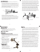
Shutter
Release
O'ring
External
Strobe Connector
Lid
Snap
Menu
LCD
Zoom
Jog Dial
Exposure Index
Focus
AE Lock
Delete
Control
Button
Back of Housing
5
C
C
l
l
o
o
s
s
i
i
n
n
g
g
t
t
h
h
e
e
H
H
o
o
u
u
s
s
i
i
n
n
g
g
1. Place housing face down in your
lap.
2. Check to see that there is an
o’ring on the housing back and
t
hat it is clean and in its proper
location.
3
. Guide the back onto the housing.
The o’ring should touch the
housing all the way around. There
should be an even gap all the way
a
round between the housing and
the housing back.
4. Lift the lid snaps so they are
extended and place the lid snap
into the hook on the housing
back.
5
. To close the housing push
down on the lid snaps until
they snap into place . Lid
snaps on opposite sides of the
housing should be closed at the
same time. Be sure they are down
far enough to engage the lock.
D
D
o
o
u
u
b
b
l
l
e
e
c
c
h
h
e
e
c
c
k
k
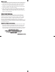
- Once the housing is closed, check the o’ring seal.
Check the gap between the housing back and the housing, it
should be even all the way around.
Look through the clear plastic back at the o’ring. You should see a
darkened area where the o’ring is compressed against the
housing back. If you do not see an even black compression seal
all the way around the back, open the lid snaps, reseat the
housing back and close the lid snaps. Visually check the seal again.
o’ring
housing back
housing back
o’ring
even gap
all 4 sides
housing
housing
7
Q
Q
u
u
i
i
c
c
k
k
-
-
R
R
e
e
l
l
e
e
a
a
s
s
e
e
B
B
a
a
s
s
e
e
,
,
H
H
a
a
n
n
d
d
l
l
e
e
s
s
a
a
n
n
d
d
T
T
r
r
a
a
y
y
Q
Q
u
u
i
i
c
c
k
k
-
-
R
R
e
e
l
l
e
e
a
a
s
s
e
e
B
B
a
a
s
s
e
e
The Quick-Release Base is
plastic. A toggle lever located
underneath the base allows
the base to be easily removed
from the Tray. Turn the
housing upside down, pull
out on the toggle lever.
Rotate the lever 90° to
remove the base.
H
H
a
a
n
n
d
d
l
l
e
e
s
s
a
a
n
n
d
d
T
T
r
r
a
a
y
y
The housing handles are
rubber and the tray is
aluminum. Their weight
helps to offset the buoyancy
of the housing. The complete
assembly is slightly negative
underwater for better
control. The handles have a
push button release for easily
attaching and removing
strobe arms. The tray and
handles can be removed from
the housing. To remove the
tray, the base must be
removed to gain access to
the nuts holding the tray on
the housing. Remove the 2
nuts, washers and rubber
spacers.
DO NOT remove the
bolts protruding through the
housing.
Quick Release Base
Slot
Flip Quick Release
Lever Up
Rotate Quick
Release Lever
Remove Quick
Release Lever
and Base
BASE QUICK RELEASE