
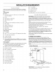
Installation guide

2.
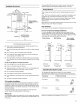
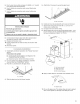
Level
the
blower
housing
with
leveling
screws
in
mounting
hooks,
using
a
level
across
bottom
of
blower
housing.
fo
=
Electrical
Connection
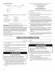
3.
Remove
the
metal
grease
filter
and
secure
the
blower
nosing
with
one
screw
in
the
bottom
hole
located
in
the
rear
INNS
]
NG
A.
Rear
of
blower
housing
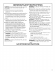
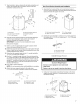
Electrical
Shock
Hazard
B.
Bottom
5 x
35
screw
hole
Disconnect
power
before
servicing.
Replace
all
parts
and
panels
before
operating.
rec’
Vent
Svsier
. . .
Onnecr
Ve
nroysiem
Failure
to
do
so
can
result
in
death
or
electrical
shock.
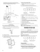
Vented
Installations
Only
1.
Disconnect
power.
1.
Fit
vent
system
over
transition
piece.
2.
Remove
terminal
box
cover.
2.
Seal
connection
with
clamps.
3.
Remove
the
knockout.
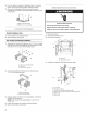
Non-vented
(recirculating)
Installation
1.
Assemble
the
3
parts
of
the
deflector
with
2
-
3.5
x
6.5
screws
provided.
The
assembled
deflector
should
be
sized
to
fit
the
fl
WO
.
Or
width
of
the
vent
cover
bracket
installed
earlier.
»
oO
B
A.
Knockout
B.
Terminal
box
cover
4.
Install
the
UL
listed
or
CSA
approved
strain
relief.
A.
Vent
cover
bracket
width
B.
Deflector
C.
3.5
x
6.5
mm
screws
2.
Connect
the
deflector
to
the
vent
cover
bracket
using
4-3.5
x
6.5
screws
provided.
A.
%"
conduit
B.
Terminal
box
cover
C.
UL
listed
or
CSA
approved
strain
relief
D.
Green
(or
bare)
wire
connected
to
yellow-green
wire
E.
White
wires
F.
Black
wires
A.
Vent
cover
bracket
B.3.5
x
6.5
mm
screws
3.
Measure
length
of 8”
(20.3
cm)
vent
needed
to
connect
the
transition
to
the
deflector.
NOTE:
Vent
should
fit
up
inside
deflector
a
minimum
of
1"
(2.5
cm).
4.
Install
vent
between
the
transition
and
the
deflector.
5.
Seal
all
connections
with
clamps.