
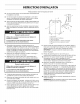
Installation guide

12
BK
Ww
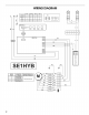
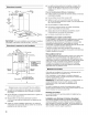
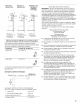
WIRING
DIAGRAM
swi
swe SW3
Sw4
Li
ight
ON
Light
OFF
re
oO
Vel1
1-3
3-5
oe
Vel2
a
2-4
46
Y-G
x
fx
fx
[OT
wt
|
ma
ne
|<
|
xlatol*<
|x
~lolo|x]*
o
*#ef
eee
Vel3
BEO6CA
cool
OU
UU
Swi
SwW2
sSw3
SW4
ES
BEO7AA
—
GY
—
Ll
B
~)
>
WwW
LOD
nema
T
Noone
Y
ANA
BU
a
a
==
>
Ss
=>
&
[|S
we
W
a]
=
BK
&
Ey,
n
zZ
eG
VW
Pe
MOTOR
CONNECTION
|
OHM
RESISTANCE
(Ohm)
rH
SPEED
TO
TERMINAL
|
BETWEEN
TERMINALS
W
1
blue(3)-white(7)
©)
2
blue(3)-red(6)
R
;
siuetagreents)
from
5.6
to
11.8
ohm
(4)
z
GY
4
blue(3)-blank(4)
3)
(T)
BU
VF
TO