
Installation guide
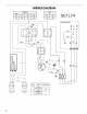
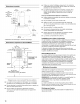
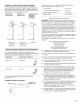

WIRING DIAGRAM
E
SLM,SLS
OFF 1 2 3
2-4 4-6 6-8 8-10
1-3 3-5 5-7 7-9
SLL
0 1
2-4 4-6
1-3 3-5
Y
Y
BK
o o 6 o_c
246811
SLM,SLS 1
1 3 5 7J !
o €_ 9
BR
&
0
U_
O0
O4 O
Y
=t
>- >-
BK
Y=G
Motor Connections Ohm resistance
speed to terminals between terminals
red-black
1 338
bridge:yellow-white
2 red-yellow 184
bridge:yellow-white
3 red-yellow 261
bridge:yellow*black
SE1L7A
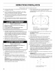
WIRING BOX
N
R
Y-G
12