30 807 01 a ,.$ WERKE ,.$® Calorimeter System C 7000 with Cooler C 7002 23(5$7,1* ,16758&7,216 Vers. 07 09.07 Reg.-No.
&( ± .21)250,7b76(5./b581* '( Wir erklären in alleiniger Verantwortung, dass dieses Produkt den Bestimmungen der Richtlinien 89 / 336 / EG und 2006 / 95 / EG entspricht und mit folgenden Normen und normativen Dokumenten übereinstimmt: DIN EN IEC 61 010-1 und DIN EN IEC 61 326-1.
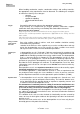
([SODQDWLRQ RI V\PEROV This symbol identifies information WKDW LV RI DEVROXWH LPSRUWDQFH WR HQVXUH \RXU KHDOWK DQG VDIHW\ Failure to observe this information may be detrimental to your health or may result in injuries. This symbol identifies information WKDW LV RI LPSRUWDQW WR HQVXUH SUREOHP IUHH WHFKQLFDO RSHUDWLRQ RI WKH GHYLFH Failure to observe this information may result in damage to the calorimeter system.
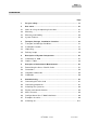
3DJH , &RQWHQWV 3DJH )RU \RXU VDIHW\ 8VHU QRWHV 2.1 Notes on using the operating instructions......................................... 2-1 2.2 Warranty ......................................................................................... 2-1 2.3 Warranty and Liability.................................................
&RQWHQWV 3DJH , 3UHSDUDWLRQ DQG &DUU\LQJ 2XW 0HDVXUHPHQWV 7.1 Recommendations for calibration ..................................................... 7-2 7.2 Notes on samples............................................................................ 7-5 7.3 Preparation for measurement .......................................................... 7-7 7.4 Carrying out a measurement.......................................................... 7-13 7.
3DJH )RU \RXU VDIHW\ In order to be able to use the appliance properly and safely, every user must first read the operating instructions and observe the safety instructions contained therein. Take care of these operating instructions and keep them in a place where they can be accessed by everyone. LQWHQGHG SXU ,QWHQGHG SXU SRVH The C 7000 calorimeter system may only be used to determine the gross calorific value of solid and liquid materials in accordance with DIN 51900 and ISO 1928.
)RU \RXU VDIHW\ 3DJH When handling combustion samples, combustion residues and auxiliary materials, the appropriate safety requirements must be observed. The following are examples of substances that may cause dangers: – corrosive – easily flammable – capable of exploding – contaminated with bacteria – toxic 2[\JHQ When working with oxygen, observe the appropriate requirements.
3DJH :H UHFRPPHQG WKDW WKH GHFRPSRVLWLRQ YHVVHO EH VHQW LQWR RXU IDFWRU\ IRU LQ VSHFWLRQ DQG UHSDLUV LI QHFHVVDU\ DIWHU HLWKHU H[SHULPHQWV RU DIWHU RQH \HDU RU GHSHQGLQJ RQ WKH DSSOLFDWLRQ HYHQ VRRQHU WKDQ WKLV 'HILQLWLRQ RI SHUVRQ ZLWK SURIHVVLRQDO WUDLQLQJ A person with professional training as defined in these operating instructions is someone 1.
IKA-WERKE C 7000 Ver. 07 09.
3DJH 8VHU QRWHV 1RWHV RQ XVLQJ WKH RSHUDWLQJ LQVWUXFWLRQV In this section you will learn how to make the most effective use of these Operating Instructions so as to be able to work safely with the calorimeter system. 7KH LQVWUXFWLRQV JLYHQ LQ 6HFWLRQ ³)RU \RXU 6DIHW\´ PXVW EH IROORZHG ZLWKRXW IDLO 6WXG\LQJ 6HFWLRQV Work through Sections 1 ... 10 in numerical order.
8VHU 1RWHV 3DJH :DUUDQW\ DQG /LDELOLW\ Please read through these Operating Instructions attentively. IKA only accepts responsibility for the safety, reliability and performance of the device if: • the unit has been used in accordance with the operating instructions; • only persons authorised by the manufacturer have carried out maintenance or repair work on the unit, and • only original parts and original accessories have been used for repairs.
3DJH 6\VWHP )HDWXUHV The C 7000 calorimeter is used for the routine determination of the gross calorific value of solid and liquid substances. The system accessories ensure that it can be individually adapted to laboratory tasks (see also Section 11). The system has the following important features: • patented double-drying measuring procedure; • short measurement time, ca.
IKA-WERKE C 7000 Ver. 07 09.
3DJH 7UDQVSRUW 6WRUDJH ,QVWDOODWLRQ /RFDWLRQ 7UDQVSRUW DQG 6WRUDJH &RQGLWLRQV During transport and storage, the system must be protected against mechanical shock, vibration, dust deposits, and corrosive atmospheres. In addition, the relative humidity should not exceed 80%. In case of repair the device has to be cleaned and free from any materials which may constitute a health hazard. If you require servicing, return the appliance in its original packaging. Storage packaging is not sufficient.
7UDQVSRUW 6WRUDJH ,QVWDOODWLRQ /RFDWLRQ 3DJH 8QSDFNLQJ Please unpack system components carefully and check for any signs of damage. It is important that any transport damage is noted during unpacking. If necessary, the damage must be assessed immediately by the transport company (post, railway or transport contractor).
3DJH 'HVFULSWLRQ RI 6\VWHP &RPSRQHQWV &DORULPHWHU & 1 2 3 & )URQW YLHZ Display Key pad Control section 1 1 2 3 4 5 6 & 5HDU YLHZ 7 8 Contrast control for display Typeplate Connection for cooler C 7002 PC connection, RS 232 Balance connection RS 232 Printer connection, Centronics Fuses Socket for mains cable with main fuse IKA-WERKE C 7000 Ver. 07 09.
'HVFULSWLRQ RI 6\VWHP &RPSRQHQWV 3DJH Commands and test parameters are entered in interactive mode using the key pad, and entries can be seen in the display. To enter parameters, there is a membrane-type key pad in the removable control section of the calorimeter. There is also an illuminated two-line display with 40 characters in each line. The display contrast can be individually adjusted using the control on the rear of the unit.
3DJH 1 2 3 &RROHU & 5HDU YLHZ Mains connection with main fuse Connection to C 7000 Cooling water connections with quickconnect couplings The cooler is used to cool the decomposition vessel quickly after a test. For this purpose, the cooler C 7002 is connected using the cable supplied to the calorimeter C 7000 (see illustrations Cooler C 7002 Rear view, Position 2, and C 7000 Rear view, Position 3).
IKA-WERKE C 7000 Ver. 07 09.
3DJH 3ULQFLSOHV RI &DORULPHWULF 0HDVXUHPHQW To make a calorimetric measurement, a sample of a substance is burnt. In order to ignite the sample, energy must be supplied from an external source. An ignition wire, which is heated to glowing point by passing an electric current through it, performs this function. If the measurement is to be accurate, it is essential that the sample is completely burnt. For this reason, combustion takes place in an atmosphere of oxygen at a pressure of 30 bar.
3ULQFLSOHV RI &DORULPHWULF 0HDVXUHPHQW 3DJH *URVV FDORULILF YDOXH +R The gross calorific value Ho is obtained by dividing the heat energy released by burning a solid or liquid fuel by the weight of the sample. When determining the heat energy released, water-containing components of the fuel must be present in liquid form after combustion.
3DJH 5HSURGXFLELOLW\ > @ (QHUJ\ LQSXW - 3UH WHVW GXUDWLRQ >PLQ@ 5HSURGXFLELOLW\ > @ 3UH WHVW GXUDWLRQ PLQ (QHUJ\ LQSXW >-@ IKA-WERKE C 7000 Ver. 07 09.
3ULQFLSOHV RI &DORULPHWULF 0HDVXUHPHQW 3DJH &RUUHFWLRQV It is intrinsic to the method that during a combustion test heat is released from external sources as well as from the sample. The ratio of heat from external sources to heat from the sample can vary considerably. +HDW RI FRPEXVWLRQ DQG H[WHUQDO HQHUJ\ The heat of combustion of the cotton thread used to ignite the sample, and the electrical ignition energy would falsify the result.
3DJH $FLG FRUUHFWLRQ Almost all substances that are tested contain some sulphur and nitrogen. Under the conditions employed for calorimetric measurements, sulphur and nitrogen burn to SO2, SO3 and NOx. In combination with water from combustion and moisture from the sample, sulphuric acid and nitric acid are formed and heat of solution is developed. The influence of the heat of solution must be taken into account when calculating the standard calorific value.
3ULQFLSOHV RI &DORULPHWULF 0HDVXUHPHQW 3DJH &DOLEUDWLRQ For the most precise results, the calorimeter should be calibrated during commissioning, following service work, when parts have been replaced, and at defined intervals. The purpose of calibration is to re-determine the thermal capacity of the calorimeter system (C value).
3DJH &RPPLVVLRQLQJ Once the components of the C 7000 calorimeter have been unpacked and brought to the location chosen for the instrument (see Chapter 3, Section 3.2 "Installation Location"), the mains lead and peripherals can be connected. &RQQHFWLQJ WKH PDLQV OHDG Check that the voltage given on the typeplate of the calorimeter corresponds to your mains supply, then plug the mains lead into the socket on the rear of the calorimeter and to the mains socket.
&RPPLVVLRQLQJ 3DJH 6ZLWFKLQJ WKH V\VWHP RQ When the mains switch is switched on, an introductory screen appears with the following text: ***** ,QWURGXFWRU\ VFUHHQ **** IKA - WERKE **** calorimetersystem C7000 VX.X **** The letters VX.X give the software version installed in the instrument. After a short pause, the display changes to the main menu, PHQX . menu 1 12:00:00 0DLQ PHQX PHQX ☞ pre-par after-p. output del.
3DJH The key pad has the following buttons: menu 1 12:00:00 pre-par after-p. f2 f1 f3 alpha 1 )LOP NH\ SDG DQG GLVSOD\ output del. f4 alpha 2 esc a 7 n b 8o c 9p mem d 4 r e 5 s f 6 ctrl g 1 u h 2v i 3w k 0 x l . y m - del t z 1. )XQFWLRQ EXWWRQV I I I I : The functions of the buttons I I I I are always indicated by the text that appears in the lower right zone of the LCD display.
&RPPLVVLRQLQJ 3DJH 5. 9 EXWWRQ ZLWK JUHHQ /(': the 9 is used to acknowledge various messages from the calorimeter. Error messages, various signals from the instrument, and results that are displayed after a measurement all have to be acknowledged. The green LED blinks when a test has been completed. After the 9 button has been pressed, the display shows PHQX again. 6.
3DJH MENU STRUCTURE FOR C 7000 CALORIMETER PHQX SUH SDU Entry of pre-test parameters DIWHU S Entry of post-test parameters RXWSXW Data output /&' Shows test data on LCD-display IUHH Information about number of tests still free WDEOH Prints tabular summary of tests VDPS Sends test data to printer GHO Erases test data PHQX PDQXDO For manual data entry KHDW FDS Manual entry of C value PHDVXUH Manual measurement (s
&RPPLVVLRQLQJ 3DJH &RQILJXUDWLRQ RI WKH & &DORULPHWHU When it is first switched on, the fundamental settings of the calorimeter should be configured. This applies to all parameters that can be set in the sub-menus of PHQX , as follows: • Sub-menu +',QLW H[W 3& For communication between the calorimeter and an external PC to operate correctly, the interface parameters and the software protocols of the two units must be consistent.
3DJH • Sub-menu 67,QLW UHDOW The parameter UHDOW (real-time print out) is used to set the time interval in seconds for sending measured values to a printer. The values 0, 3, 12, or 24 seconds can be set. The preset value is 0 seconds . If the value 0 is selected, the transmission of readings to a printer) during a test is switched off. The presentation of data on the LCD-display is unaffected by the setting of this parameter.
&RPPLVVLRQLQJ 3DJH ☞ ,JQLWLRQ WLPHV WKDW DUH WRR ORQJ FDQ FDXVH GHVWUXFWLRQ RI WKH LJQLWLRQ ZLUH RU LQFUHDVHG ZHDU DQG WHDU ([DPSOHV RI HQWULHV For all entries that you may need to make on the calorimeter, the three examples in presented this section are representative: • • • Setting the time Setting the time interval for output of results Configuration for a balance All three examples assume that the C 7000 calorimeter has been switched on, and that PHQX of the main menu is shown in the
3DJH e Use function key I to call up the sub-menu WLPH; by doing so you have reached the lowest Level of the menu structure. The LCD-display is now prepared for entering the time. hhmmss(hour/minute/second) HDInit 081532_ f Press the GHO button six times to erase the time currently entered (here: 8 h: 15 min: 32 sec.), which at the same time moves the cursor to the left. Use the alpha-numeric keys to enter the correct time in the format given in the first line (hhmmss).
&RPPLVVLRQLQJ 3DJH e Use function key I to call up the sub-menu UHDOW ; by doing so you have reached the lowest Level of the menu structure. The LCD-display is now prepared for entering the time interval for output of readings during a test. The value currently set is shown in the left-hand zone of the second line of the LCD-display, and the values that can be selected, 0, 3, 12 and 24 seconds, are given in the right-hand zone.
3DJH e Use function key I to call up the sub-menu EDODQFH; by doing so you have reached the lowest Level of the menu structure. The LCD-display is now prepared for selecting the required EDXG UDWH. baud-rate f HDInit 1200 2400 4800 9600 I I I I Use one of the function keys I , I , I or I to select the desired value. Your choice is then shown in the left-hand zone of the second line of the LCD-display. g Press the display. ↵ button.
IKA-WERKE C 7000 Ver. 07 09.
3DJH 3UHSDUDWLRQ DQG &DUU\LQJ 2XW 0HDVXUHPHQWV The term "measurements" as used here means both measurements for calibrating the instrument (calibration measurements) and measurements made to determine a gross calorific value. The difference lies mainly in the evaluation of the results, preparation and execution are almost identical for both types of measurement.
3UHSDUDWLRQ DQG &DUU\LQJ 2XW 0HDVXUHPHQWV 6HLWH g 0HDVXUHPHQW In the C 7000 calorimeter, measurement is fully automatic. h &RROLQJ The decomposition vessel is removed from the C 7000 calorimeter and placed in the C 7002 cooler, where it is automatically cooled to the temperature of the calorimeter. i 9HQW The decomposition vessel is vented using the C 7010.8 vent handle or venting station C 7030. j &OHDQ Clean and check the decomposition vessel as described in Section 7.6.
3DJH ☞ ,I VHYHUDO GHFRPSRVLWLRQ YHVVHOV DUH XVHG LQ D PHDVXULQJ FHOO WKH KHDW FD SDFLW\ RI WKH V\VWHP PXVW EH GHWHUPLQHG E\ FDOLEUDWLRQ ZLWK HDFK GHFRPSRVL WLRQ YHVVHO $ GHFRPSRVLWLRQ YHVVHO PXVW RQO\ EH XVHG LQ D PHDVXULQJ FHOO LQ ZKLFK LW KDV EHHQ FDOLEUDWHG Calibration must be carried out under conditions similar to those that will be used for subsequent tests. If combustion tests are to be carried out with absorption liquid (e.g.
3UHSDUDWLRQ DQG &DUU\LQJ 2XW 0HDVXUHPHQWV 6HLWH &RGLQJ When working with the calorimeter, up to a maximum of 8 decomposition vessels can be used. This is made possible by giving the decomposition vessels code numbers from 0 to 7. The calorimeter then recognises automatically which vessel is being used for a test, and selects the correct calibration parameter. Coding is carried out by separating the narrow printed-circuit conductors on the board mounted on the base of each decomposition vessel.
3DJH 1RWHV RQ VDPSOHV 'HFRPSRVLWLRQ YHVVHOV & DQG & DUH QRW SHUPLWWHG IRU H[SHULPHQWV RQ IXHO VDPSOHV FDSDEOH RI H[SORGLQJ 1RWH LQ WKLV UHJDUG &KDSWHU ³)RU \RXU VDIHW\´ The individual parts, and in particular the threading of the decomposition vessel must be checked regularly for wear and corrosion. Note in this regard Operating Instructions C 7010 or C 7012.
6HLWH 3UHSDUDWLRQ DQG &DUU\LQJ 2XW 0HDVXUHPHQWV culated. The quantity of this external energy must be known for the calculation, and must be entered with the pre-test parameters (SUH SDU) as T H[WU . The quantity of combustion aid used should be kept as small as possible. $FLG IRUPDWLRQ KHDW RI VROXWLRQ ☞ Almost all substances to be analysed contain some sulphur and nitrogen. Under the pressure and temperature conditions in the decomposition vessel, they burn to form SO2, SO3 and NOx.
3DJH 3UHSDUDWLRQ IRU PHDVXUHPHQW 1 2 3 4 5 6 7 8 &RPSRQHQWV RI WKH GHFRPSRVLWLRQ YHVVHO Connection for filling with oxygen Lid Screw-on cover Electrodes Ignition wire Crucible holder Crucible Support for combustible crucible For protection against corrosion, the lining of the decomposition vessel is made of stainless steel. The decomposition vessel must be clean and dry, because all foreign materials, in particular water, affect the heat capacity and thus the results.
3UHSDUDWLRQ DQG &DUU\LQJ 2XW 0HDVXUHPHQWV 6HLWH ,I VHYHUDO GHFRPSRVLWLRQ YHVVHOV DUH EHLQJ XVHG LW LV LPSRUWDQW QRW WR PL[ XS WKHLU SDUWV VHH HPERVVLQJ RQ WKH SDUWV The following steps are required to prepare the decomposition vessel: c 2SHQ WKH GHFRPSRVLWLRQ YHVVHO Unscrew the cover and take out the lid. To do this, engage the carrying and venting handle, C 7010.8, and lift the lid vertically upwards.
3DJH e :HLJK WKH VDPSOH ZLWK FRPEXVWLEOH FUXFLEOH LI XVHG $V D UXOH WKH TXDQWLW\ ZHLJKHG VKRXOG EH VXFK WKDW WKH PD[LPXP SHUPLVVLEOH HQHUJ\ LQSXW RI - LV QRW H[FHHGHG )DLOXUH WR REVHUYH WKLV UXOH PD\ UH VXOW LQ GDPDJH WR WKH FDORULPHWHU V\VWHP 7KH WHPSHUDWXUH LQFUHDVH GXULQJ D WHVW VKRXOG EH DV FORVH DV SRVVLEOH WR WKH WHPSHUDWXUH LQFUHDVH GXULQJ FDOLEUDWLRQ ,I WKH GHFRPSRVLWLRQ YHVVHO LV GDPDJHG WKHUH LV D GDQJHU RI LW EXUVWLQJ )ROORZ WKH RSHUDWLQJ LQVWUXFWLRQV IRU WKH GHFRPSRVLWLRQ
3UHSDUDWLRQ DQG &DUU\LQJ 2XW 0HDVXUHPHQWV 6HLWH g Close the decomposition vessel C 7010 oder C 7012 Place the cover onto the lower section and push down until it presses against the stop piece in the lower section. C 7010/ C 7012 Place the union nut onto the lower section and tighten by hand. The decomposition vessel can now be filled. h Finally, the decomposition vessel is filled with oxygen at 30 bar using the C 48 IKA oxygen filling station.
3DJH c Starting from PHQX , for a calibration, press the button once to go to PHQX . Then press function key I , to enter the sub-menu FDOLE. For a calorific value determination, press function key I in PHQX to go to sub-menu SUH SDU. In both submenus, the enquiry VDPSOH FRGH appears. d The VDPSOH FRGH identifies a test. Use of this code word will later provide access to the test data. A specified sample code will appear in the upper left zone of the LCDdisplay for all further entries.
3UHSDUDWLRQ DQG &DUU\LQJ 2XW 0HDVXUHPHQWV 6HLWH g Here the user also has the choice of manual entry or automatic input from a connected balance. Manual entries are made directly in this window using the alphanumeric keys, or automatic input is called up by pressing function key I . The mass weighed by the balance is automatically accepted. After entry, confirm by pressing the ↵ button.
3DJH &DUU\LQJ RXW D PHDVXUHPHQW When a calibration or a calorific value determination has been prepared as described above, the measuring process can be started. The VDPSOH FRGH shown on the LCD-display informs you of the test parameters which will be used for the measurement. Pressing the ↵ button starts the calibration or calorific value determination. From now on, the C 7000 calorimeter takes control. The measurement process is made up of a pre-test and the main test.
3UHSDUDWLRQ DQG &DUU\LQJ 2XW 0HDVXUHPHQWV 6HLWH f Venting the decomposition vessel, which may contain poisonous gases should be carried out using the venting station, C 7030, which is available as an accessory. If the decomposition vessel is vented using the handle, C 7010.8, this must be done in a fume cupboard. Make sure the decomposition vessel is completely vented to atmospheric pressure, otherwise it cannot be opened.
3DJH i Then press the PHP button to store your new entry, and use the HVF button to return to PHQX in the main menu. The C value for the decomposition vessel you have specified is now stored in the calorimeter, and will be called up automatically when you make a measurement with this vessel. Repeat the above procedure to enter the C value for all the other decomposition vessels you are using.
IKA-WERKE C 7000 Ver. 07 09.
3DJH (YDOXDWLRQ RI &DORULILF 9DOXH 7HVWV When a calorific value test has been completed, you can proceed to evaluating the results. Section 8.1 explains how stored tests can be listed in a table, how you output or erase test results, and how you can list information about free memory for storing new tests. You will find these functions in the sub-menu RXWSXW. The test results are dependent on the post-test parameters; their meaning and how to enter them are described in Section 8.2. Section 8.
(YDOXDWLRQ RI &DORULILF 9DOXH 7HVWV 3DJH ([DPSOH selection of all test data for the month of December in the year 2000: • the selection criterion for the date is " 1200". In this way, all the days of the month, the 12th.
3DJH 2XWSXW RI WHVW GDWD It is only possible to calculate net calorific values and publish them by printing or on the LCD-display after all pre-test and post-test parameters have been entered DQG the measurements carried out. The output contains all the parameters entered, the automatically recorded data, and the calculated results. The latter are dependent on the calculation mode selected. In addition, the output contains notes about the test, if appropriate.
(YDOXDWLRQ RI &DORULILF 9DOXH 7HVWV 3DJH To edit the parameters of a particular test, proceed as follows: c Change from PHQX to the sub-menu HGLW , by pressing function button I . d Enter the sample code to identify the test you wish to change. e Use the or corrections. buttons to go to one or more parameters and make the desired f Store the new entries by pressing the PHP button. If you want to break off the procedure, press the HVF button. Changed values will then not be stored.
3DJH as delivered condition are marked "raw", and parameters that refer to the analytically moist condition are indicated by "an". By calling up the sub-menu DIWHU S under PHQX , the various parameters can be entered in order in the same way as the pre-test parameters (see Section 7.3). The values entered must be stored by pressing the PHP button. After they have been stored, the data can only be changed by using the HGLW menu.
(YDOXDWLRQ RI &DORULILF 9DOXH 7HVWV 3DJH K\JU PRLVWXUH DQ VXOSKXU DQ Percentage of water from hygroscopic moisture Calculation modes: FRDO W FRDO W Percentage of sulphur Calculation mode: FRDO W 7HVW VLPXODWLRQ In some cases, it is helpful to run through calorific-value tests or to calculate possible test results without actually carrying out a combustion test. Under PHQX PDQXDO PHDVXUH you can enter the temperature increase of a test manually.
3DJH &DUH DQG 0DLQWHQDQFH 0DLQWHQDQFH To ensure proper functioning of our instrument in continuous use, it is essential that it is maintained at regular intervals. We can offer you a special maintenance contract to meet this need. You can obtain further information direct from our Service Department.
IKA-WERKE C 7000 Ver. 07 09.
3DJH 0HVVDJHV DQG 7URXEOHVKRRWLQJ The C 7000 calorimeter is subjected to stringent quality checks during manufacture, should malfunctions occur despite this care, you will find in this section a selection of corrective measures for dealing with a range of fault situations. Most messages and fault indications appear on the LCD-display. They should be acknowledged with the 9 button.
0HVVDJHV DQG 7URXEOHVKRRWLQJ 3DJH 0HVVDJH &DXVH 5HPHG\ QR LQFUHDVH LQ WHPSHUDWXUH 12 seconds after the start of the main test, the temperature increase is less than 0.2 K. PHDVXUHPHQW UDQJH H[FHHGHG PHDVXUHPHQW FDUG GHIHFWLYH PHDVXUHPHQW DOUHDG\ SHUIRUPHG 0HDVXUHPHQW VWDUWHG SRVW WHVW SDUDPHWHUV DOUHDG\ HQWHUHG QR PHDVXUHPHQW SHUIRUPHG \HW VDPSOH FRGH LV DVVLJQHG VDPSOH FRGH QRW IRXQG PHPRU\ IRU WHVWV IXOO Faulty ignition or vessel not filled with oxygen.
3DJH 0HVVDJH WHVW QRW \HW SULQWHG ORVV RI SRZHU VXSSO\ 37 SDUDPHWHUV PLVVLQJ 9 WLPHG RXW VFDOH WLPHG RXW PHPRU\ KDV EHHQ UHLQLWLDOL]HG SUREOHP ZLWK FORFN VWRUDJH FORFN EDWWHU\ GHDG &DXVH 5HPHG\ You have attempted to change the parameters of a test that has not yet been printed out. Print test at least once, and then edit. An interruption in the power supply has been detected. Possibly too many consumers are connected to a single socket, which has caused a brief voltage drop.
0HVVDJHV DQG 7URXEOHVKRRWLQJ 3DJH )DXOW ZLWKRXW VLJQDO IURP &DORULPHWHU )DXOW &DXVH 5HPHG\ FDORULPHWHU LQ XQGHILQHG VWDWXV Power supply failure If a test was not being carried out, switch the system off and on again to restart it. If a test was in progress, adopt the following procedure: • switch the system off and restart correctly; • remove the decomposition vessel, release the pressure in it, and prepare for a new test. Quantity of oxygen in bomb was not sufficient.
3DJH $FFHVVRULHV DQG &RQVXPDEOHV $FFHVVRULHV 2UGHULQJ GHVFULSWLRQ C 7010 C 7012 C 5010.4 C 48 C 7002 C 7010.8 C 7030 C 5040 C 21 C 29 KV 500 IKA decomposition vessel, standard IKA decomposition vessel, halogen resistant Support for disposable crucible Oxygen filling station Cooler Venting handle Venting station Calorimeter software for PC (CalWin) Pelleting press Pressure reducer for oxygen Cooling water supply &RQVXPDEOHV 2UGHULQJ GHVFULSWLRQ C 710.4 C 5010.3 C 5012.3 C 5010.
IKA-WERKE C 7000 Ver. 07 09.
3DJH 7HFKQLFDO 'DWD 7HFKQLFDO GDWD IRU & &DORULPHWHU Operating voltage Operating frequency Power consumption Fuses for 230 V supply: for 115 V supply: Degree of protection to DIN 40 050 Protection class Over-voltage category Contamination level Ambient temperature Max. relative humidity of environment Use above sea level Dimensions (B x D x H) unit closed: unit open: Weight Measuring range Interfaces 100 V-120 V / 220 V-240 V 60 / 50 Hz 100 W 2 x 1.
IKA-WERKE C 7000 Ver. 07 09.
3DJH ,QGH[ $ , Acetobutyrate capsules ......... 5-5, 7-5 Acid formation................................7-5 Ignition time................................... 6-7 Incomplete combustion ............... 7-12 Interface parameters ..................... 6-6 Introductory screen ....................... 6-2 % Balance.................................. 6-1, 6-6 Benzoic acid ..................................5-6 & C value...........................................7-2 Calculation mode ...................
IKA-WERKE C 7000 Ver. 07 09.