43 459 00 a IKA® C 6000 global standards IKA® C 6000 isoperibol Operating instructions 052014 Reg.-No.
Source language: German EN Contents Page CE Declaration of conformity Explication of warning symbols Safety instructions Correct use User instructions System features Warranty and liability Transport and storage Transport and storage conditions Unpacking Scope of supply Description of system components IKA® C 6000 calorimeter global standards/isoperibol Hoses Commissioning Place of installation Connection to the condenser Connection to the water Connection to the oxygen supply Connection to the mains powe
Other Settings Evaluation Measurement Ignition aids Combustion aid Balance Printer Other Help and servicing system Displaying / hiding the sample rack Cleaning Cleaning the system Cleaning the filter Troubleshooting Fault rectification Checks Accessories and consumables Accessories Technical data Technical data IKA® C 6000 global standards Technical data IKA® C 6000 isoperibol 38 38 39 40 41 41 42 42 44 46 48 48 48 49 51 55 56 56 57 57 59 EC-Declaration of conformity We declare under our sole responsibility
Safety instructions Read the operating instructions in full before starting up and follow the safety instructions. Keep the operating instructions in a place where they can be accessed by everyone. Ensure that only trained staff work with the appliance. Follow the safety instructions, guidelines, occupational health and safety and accident prevention regulations.
The decomposition vessel is manufactured in accordance with the directive for pressure equipment 97/23/EC. This is indicated by the CE symbol with the ID number of the notified body. The decomposition vessel is a category III pressure device. The decomposition vessel has undergone an EC prototype test. The CE declaration of conformity confirms that this decomposition vessel corresponds to the pressure device described in the EC prototype test certificate.
Correct use The IKA® C 6000 global standards/isoperibol calorimeter system is used for calorific value determination of solid and liquid substances. This is done by placing a known quantity of a substance in a decomposition vessel which is surrounded by a water jacket. The sample is then combusted in an oxygen atmosphere . The calorific value of the sample can then be calculated from the resulting increase in temperature, the sample mass and the known thermal capacity of the overall system.
• Operating mode based on the adiabatic, isoperibolic or dynamic principle at 22 °C, 25 °C or 30 °C (the beginning temperature of the water in the inner vessel) depending on the cooling water temperature.
Unpacking Please unpack the system components carefully and check for any damage. When you unpack the equipment, check for any damages which may have occurred during transportation. In the case of any damage a fact report must be sent immediately (post, rail or forwarder). Scope of supply Calorimeter IKA® C 6000 global standards/isoperibol • • • • • • • • • • • Calorimeter IKA® C 6000 global standards/isoperibol Attachment set Stylus for touch screen operation Discharge hose (1.
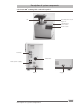
Description of system components Calorimeter IKA® C 6000 global standards/isoperibol Lift Decomposition vessel Stylus for operating the touch screen Touch Screen Interfaces Water filter Mains power supply Water Oxygen 10 Description of system components
Hoses • • Discharge hose (empty) Inflow pipe (in) • Return pipe (out) • Venting hose (out) • C 6000 Condenser C 6000 C 6000 O2 connection tube (in) M8 M8x1 M6 C 6000 Commissioning Place of installation A constant ambient temperature is an important requirement for ensuring the high measuring accuracy of the system. The following conditions must therefore be fulfilled at the place of installation: • No direct solar radiation • No draughts (e.g.
Connection to the condenser Rear view without hoses attached Make sure the filter casing is always securely closed (see „Servicing and cleaning the filter“)! Insert the inflow pipe into the „IN“ port until it clicks home. Connect the other end of the pipe to the „OUT“ port of the condenser (water pressure max 1.5 bar). Insert the return pipe into the „OUT“ port until it clicks home. Connect the other end of the pipe to the „IN“ port of the condenser.
Connecting the oxygen supply Insert the O2 connection tube into the calorimeter „IN“ port until it clicks home and connect the free end to the pressure reducer, using the adapters supplied if necessary. IKA® C 29. Removal entails the same operations performed in the reverse sequence. Note: The O2 connection tube can be removed only after it has been depressurised.
Connection of peripherals Note: While the peripheral devices are being connected, they and the calorimeter must be turned-off on the mains power switch! RS232 PC: Serial connection for controlling the calorimeter using CALWIN or operating with serial printer C1.50.
On/off switch The device is switched on and off via the on/off switch located on the righthand side. Switch the device off at the on/off switch. � Lift moves upwards. Switch the appliance off only by using the menu commands. � Lift moves downwards. Data may be lost if the appliance is switched off other than by following the menu commands. ATTENTION Note: Switch the device off at the on/off switch only when directed to do so by the menu command.
Display and operating elements After the IKA® C 6000 global standards/ isoperibol calorimeter has been switched on, the touch screen display is active and can be operated using the stylus or finger. Explanation of the screen display Schematic representation of he display components C A D E D F G G I Pos.
The contents of the screen display are often distributed over several tabs. You can switch between tabs at any time by clicking on them. Thus for instance the screen display during the calorimetric standard procedure consists of the three views „Measurements“, „Device“ and „Graphics“. List display Status symbols Green tick Measurement completed but not yet evaluated, or selection acknowledgement. Pocket calculator Measurement completed end evaluated, evaluation inputs can no longer be changed.
The view „Graph“ shows the temperature by time. The most important actions available at any point in time are gathered together as clickable buttons along the bottom edge of the screen. Switch Switch Selection box To initiate an action it is sufficient to click on one of the discrete areas showing the relevant images or text. For instance during the „Preparation for measurement“ dialogue the most important actions are explained below.
Weighted sample Input of a numerical value, such as weighted sample: The entire area with the exception of the „Balance“ button is available to be clicked here. A numerical virtual keyboard is opened and can be used to input the value: After the virtual keyboard has been closed with „OK“, the value in the input field is loaded. Alternatively, clicking on the „Balance“ button automatically loads a value from a connected balance.
Working with the IKA® C 6000 global standards/isoperibol calorimeter Switching on the device The IKA® C 6000 global standards/isoperibol is switched on with the On/off switch. The cover opens automatically. A start screen appears for about 30 seconds, during which the hardware is initialised and the software is loaded. System test The system test is performed automatically every time the IKA® C 6000 global standards/isoperibol is switched on.
If the cooling water conditions are not correct for the selected function of the IKA® C 6000 global standards/isoperibol, you can select a different function from those currently available. Make sure however that the system conditions are stable. The following are the default modes that are set: - Adiabat 22 (IKA® C 6000 global standards) - Isoperibol 22 (IKA® C 6000 isoperibol) First commissioning At first commissioning you must register a decomposition vessel: To do this, press „Menu on“ button.
Die kalorimetrische Standardprozedur Determining the calorific value Test condition Combustion is carried out in a calorimeter under specifi c conditions. The IKA® C 6000 global standards/isoperibol is filled with a weighed fuel sample, the fuel sample is ignited and the temperature increase in the calorimeter system measured.
Corrections As determined by the system, during a combustion experiment, not only is heat generated from the combustion of the sample, but heat also occurs in the form of extraneous energy. This may fluctuate considerably in proportion to the heat energy of the fuel sample. The combustion heat of the cotton threat that ignites the sample and the electrical ignition energy would result in distorted values of the measurement. This effect is taken into consideration in the calculation with a correction value.
Note on the sample The calorimeter system IKA® C 6000 global standards/isoperibol is a precision measuring instrument for the routine determination of calorific values of solid and liquid substances. Exact measurements can however be achieved only if the individual steps of the trial are performed with care. The procedure as described in the „For your safety“ section and in the following sections must therefore be adhered to exactly.
Complete combustion To correctly determine the gross calorific value, it is of fundamental importance that the sample undergoes complete combustion. After each experiment, the crucible and all solid residues must be examined for any signs that combustion was not complete. In case of using substances tending to squirt it is not possible to ensure complete combustion.
Calibration To ensure precise, reproducible results of the measurement, the calorimeter system is calibrated after it is initially placed in service, after service jobs, after parts are replaced and at specific time intervals. During calibration, the heat capacity of the calorimeter system is redetermined. Depending on the standard used, determination of the thermal capacity may require performance of several measurements.
Preparing measurements The term „measurements“ below refers to both the measurements to calibrate the calorimeter system (calibration measurements) and the actual measurements for determining the calorific value. The difference lies mainly in the evaluation (see the section „Working with the device“ and „Settings“), whilst preparation and performance make virtually no difference. The following preparations must be performed in order to prepare the system to take a measurement: of the calibration (max.
Click on the necessary figures and the decimal point, and press OK to confirm the input. You can also load the weight from a connected balance or request it by clicking on the „Balance“ button. The value is then entered automatically. All other inputs are optional. The default is that the decomposition vessel is not selected manually but is identified when it has been hung in the calorimeter. Note: weight must be < 5 g.
You can input values between 0 and 20,000 Joules for „External energy 2“. You can also select specific types of combustion aids from the list. In such cases you must enter the weight of this combustion aid so that the external energy can be calculated. You can also load these weights directly from a balance: The most flexible way is to click on the relevant „Balance“ button. The value is then loaded to the right place.
After the preparation for measurement, a message appears requiring secure closure of the decomposition vessel, despite there being no decomposition vessel hung in the calorimeter cover. You should acknowledge the message when you have hung the decomposition vessel in the calorimeter cover. If you accidentally press the „Start“ button before you have hung a decomposition vessel in the calorimeter you will receive an error message when you close the calorimeter cover.
The screen switches to the „Device“ tab. You can trace the progress of the measurement both in this tab and also in the „Graphics“ tab. In the area above the record, progress bars for the individual phases of the measurement are shown. Once the measurement has been correctly completed the calculated calorific value and the calculated thermal capacity also appear here. You can cancel the measurement at any time by clicking on „Cancel“.
Evaluation Click on auf the measurement to be evaluated. Then click on the „Evaluation“ button. The following screen with several tabs appears. The parameters for the evaluation are distributed across the „Calorific value“ and „Heat value“ tabs. Note: The „Heat value“ tab is not shown at calibration. Now you can input the parameters required for the standard that was selected (here: DIN 51900 (2000)).
Menu Click the „Menu on“ button to display the menu. Use the scroll bar to display all the menu options. If a measurement has been prepared or selected you will see only a restricted selection of the menu options. „Display/hide information field“: an information field above the button toolbar is displayed or hidden. „Help“: This added the „Help“, „Servicing“ and „Hardware details“ tabs to the screen view and displays an information window with system information.
Library The library screen shows all the measurements within the memory location \FFSDISK\C6000\ tests. In the left hand selection field you can also extend an directory tree which is organised by years and months. Within each month the right hand window then displays the measurement organised by days. Select the desired day and click on the „Evaluation“ button. The list of the measurements on the selected day is displayed.
Alternatively you can use the actions provided by the menu as described above. Once you have completed the work on the measurements for the selected day, switch back to the „Library” tab. Once you have completed all the library work, click on the „Back“ button. Working Mode, Vessels and Calibrations For management of the decomposition vessels and their associated settings, click on the „Menu“ button and then the menu item „Function, decomposition vessels and calibration“.
If you wish to change the function for subsequent measurements, click on the „Change“ button to start the system check for the new function. Alternatively you can select a decomposition vessel from the updated list of decomposition vessels. „Calibration“ tab You can select each calibration individually and click on the „Select“ button, or double click on the calibration to reference this calibration in the calculation of the C mean value (or to exclude it if it had previously been selected).
„Check chart“ tab This displays the graphics for the selected calibration with the upper and lower warning and control limits. The scaling is adapted automatically. LWL/UWL and LCL/UCL The LWL and UWL (lower and upper warning limits) define the area within which 95% of the calibration measurements should lie. The LCL and UCL (lower and upper control limits) define the area within which 99.7% of the calibration measurements must lie in order for the device to fulfil statistical controls.
New decomposition vessel: click on the „New decomposition vessel“ button to assign a new decomposition vessel to the calorimeter. Place the new decomposition vessel over the sensor face. The RFID tag is detected and displayed in the „RFID field (automatic decomposition vessel detection“. Click on the „Serial number“ field and enter the engraved serial number for the new decomposition vessel. Finally click on the „Add“ button. Please note that the addition of a new decomposition vessel cannot be undone.
Select from the list: The selected standard will be applied to all the subsequent measurements. Evaluated measurements will comply with this standard: if a measurement has already been evaluated, the evaluation procedure will be used for any subsequent re-evaluation. Otherwise the current setting for the evaluation procedure will be used. Measurements evaluated previously are not affected by this change. Display unit: this sets the display units for the calorimetric results. Select them from the list.
Load parameters: Some parameters from the previous measurement (Name, User, Properties, ignition and combustion aid) can be retained when preparing for a new measurement. No venting: The venting of the decomposition vessel after measurement is skipped in order to facilitate determination of the products of combustion. Restart: If a measurement is cancelled prior to ignition, after rectifying the cause of the cancellation you can restart the measurement without having to prepare a new measurement.
Combustion aid „Combustion aids“ tab There are two different combustion aids available for use in order to achieve correct combustion of samples. The external energies contributed by the aids are input or calculated at preparation of the sample and are included automatically in the calculation of the calorific values. A list is provided for the most commonly used combustion aids, showing their calorific values.
Printer „Printer“ tab Select a suitable printer from the list. USB PCL printer You can connect many type of USB printers which the use the PCL printer language to the C 6000. We recommend the HP Business Inkjet 1200 or its successor models. Network printer When you have selected a network printer you must then input the network address of the printer. In addition the C 6000 must be connected to the company‘s network. Serial printer A serial printer can be connected to PC port of the C 6000.
Speaker: Activation of the speakers.
Help ans servicing system Help You can activate and display the „Help“ tab at any time to obtain detailed information on the current status and available actions for the calorimeter. Click on either the „Help“ button in the information field or on the „Help“ menu item and switch to the „Help“ tab. The „Hardware details“ and „Servicing“ tabs are also displayed as well as the „Help“ tab. The left hand selection field displays an extendable list of all statuses, views and fault options.
Empty: The inner vessel can be emptied manually. Stirrer: Here the operation of the stirrer can be tested. After the start the stirrer speed is displayed. Cooling water: After the start the current cooling water temperature at the entry into the calorimeter is displayed. Cover up/down: The cover can be opened and closed manually. RFID: After the start the decomposition vessel detection is activated and the RFID code of the decomposition vessel can be read. Click on „Stop“ to stop the function test.
Displaying/hiding the sample rack Working with the sample rack To work with the sample rack you must first check that it is connected to the calorimeter. Open the “Sample rack” screen from the main menu. After this you can use the „Use sample rack“ menu item to activate/ deactivate its use. A schematic representation of the assignment of the rack is displayed in the upper area of the menu.
CAUTION: Before each weighing and transfer of values from the balance, the “TARE” key needs to be pressed. If the crucible is placed in the sample rack, the input field is closed automatically and the prepared measurement appears in the measurement window. If the crucible is now removed from the sample rack, the input field opens once more and combustion aids can be added (if this has not already been done). If entries have already been made the input field is deactivated.
You can prepare a maximum of 12 measurements in the sample rack, and process them in any order. The assignment remains saved even when the IKA® C 6000 global standards/isoperibol calorimeter is switched off. If a crucible unsuitable for the specified procedure is set or taken out, a message appears and the action must be reversed.
Cleaning • Switch the device off. • Switch the cooling water supply off (switch off the condenser, clock the water shut-off valve). • Disconnect the hoses from the device. • Have an absorbent cloth ready to hand. • Turn the filter casing anticlockwise, some water will escape. wipe up the water with the cloth. • Pull out the sieve. • Use a suitable brush to clean the sieve inside and out. • Place the sieve back in the filter. • Screw the filter casing on again finger-tight.
In certain exceptional cases the fault may prevent the calorimeter being available for measurements. In such cases the calorimeter initiates a system test directly the „Acknowledge“ button is clicked. After you have taken the actions described in the Help or in the operating instructions, click on the „Restart“ button to start the system test. On successful completion of the system test the IKA® C 6000 global standards/isoperibol is again available for measurements.
Fault rectification Display Description What should be done? What happens next? No heating pulse in the inner circuit. No increase in temperature Acknowledge the alarm. within the inner water circuit. Check the cooling water flow Check the circulating pump. Click on „Restart“ to repeat the system test. Click on „Next“ to skip the system test. No increase in temperature Acknowledge the alarm. within the outer water circuit. Check the cooling water flow Check the condenser and the water inflow.
Display Description No increase in temperature after This error message is generated, ignition. if the increase in temperature has not achieved the specified value within the first minute after ignition. What should be done? What happens next? Acknowledge the error message to revert to the „Wait“ message. The sample is combusted. The weighted sample of the sample may be insufficient. The calorific value of the sample is too small, use a combustion aid.
Display Description What should be done? What happens next? Water not filling OK. The system could not completely fill the inner vessel with water completely within the specified period of time. Acknowledge the error message to revert to the „Wait“ message. Water level in the condenser too low. Water flow rate insufficient. Defect at the water sensor. The water sensor shows comple- Acknowledge the error message tely full within a very short time. to revert to the „Wait“ message.
Display Description Controller alarm The reliable regulation of the outer vessel is a major precondition for good quality measured values. Any error message from the controller brings the current measurement to an end and demands a system test. Further work using the calorimeter can be performed only once the system test has been completed successfully. What should be done? What happens next? Acknowledge the error message in order to switch to the „System Check“ status. Press the „Restart“ button“.
Checks Various major parts of the calorimeter are monitored. Information about when the servicing intervals defined by the manufacturer for these parts fall due is shown in the information field, with the invitation to perform servicing actions. You must then confirm performance of the servicing actions. Click on „Acknowledge“ to acknowledge performance of the servicing actions.. The acknowledgement is saved and can be checked by the Service Engineers.
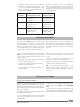
Accessories and consumables Accessories C 6010 C 6012 C 5010.5 C 5010.8 C 21 C 5020 C 29 C 6030 C 27 C 5041.10 C 6040 C 1.50 C 60.1020 Decomposition vessel Decomposition vessel Crucible holder, large Crucible holder, small Pelleting press Sample rack Pressure reducer, oxygen Gas washing station Calorimeter instrument set Connecting cable 9-pin / 3m Calwin Dot-matrix printer Organiser Consumables C 723 C 723 C 43 C 710.4 C 710.8 C 16 C 17 C 15 C9 C 10 C 12 A C 12 AOD 1.11 AOD 1.12 C 1.103 C 1.
Technical data IKA® C 6000 global standards Measuring range max. ..................................................................................... J ................................................ 40000 Measuring mode adiabatic 22 °C .............................................................................................................................yes Measuring mode dynamic 22 °C ...................................................................................................................
Evaluation to ASTM D5865 ......................................................................................................................................yes Evaluation to ASTM E711 .................................................................................. .....................................................yes Evaluation to ISO 1928 ............................................................................................................................................
IKA® C 6000 isoperibol Measuring range max. ..................................................................................... J ................................................ 40000 Measuring mode dynamic 22 °C ...............................................................................................................................yes Measuring mode isoperibolic 22 °C ..........................................................................................................................
Evaluation to ASTM D5865 ......................................................................................................................................yes Evaluation to ASTM E711 .................................................................................. .....................................................yes Evaluation to ISO 1928 ............................................................................................................................................
IKA® - Werke GmbH & Co.KG Janke & Kunkel-Str. 10 D-79219 Staufen Tel. +49 7633 831-0 Fax +49 7633 831-98 sales@ika.de www.ika.