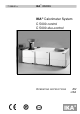
71 900 01 a ,.$ WERKE ,.$® Calorimeter System C 5000 FRQWURO C 5000 GXR FRQWURO 23(5$7,1* ,16758&7,216 Vers. 10 04.07 Reg.-No.
&( ± .21)250,7b76(5./b581* '( Wir erklären in alleiniger Verantwortung, dass dieses Produkt den Bestimmungen der Richtlinien 89 / 336 / EG und 73 / 23 / EG entspricht und mit folgenden Normen und normativen Dokumenten übereinstimmt: DIN EN IEC 61 010-1 and DIN EN IEC 61326-1.
([SODQDWLRQ RI V\PEROV This symbol identifies information WKDW LV RI DEVROXWH LPSRUWDQFH WR HQVXUH \RXU KHDOWK DQG VDIHW\ Failure to observe this information may be detrimental to your health or may result in injuries. This symbol identifies information WKDW LV RI LPSRUWDQW WR HQVXUH SUREOHP IUHH WHFKQLFDO RSHUDWLRQ RI WKH GHYLFH Failure to observe this information may result in damage to the calorimeter system.
3DJH , 7DEOH RI &RQWHQWV 3DJH )RU \RXU VDIHW\ 2.1 2.2 2.3 8VHU QRWHV Notes on using the operating instructions....................................... 2-1 Warranty ....................................................................................... 2-1 Warranty and liability..................................................
7DEOH RI &RQWHQWV 3DJH , 'HWHUPLQLQJ JURVV FDORULILF YDOXHV 10.1 Notes on the sample ................................................................... 10-1 10.2 Acid correction ............................................................................ 10-2 10.3 Procedure for determining gross calorific value ............................ 10-3 10.4 Cleaning the decomposition vessel .............................................. 10-6 10.
3DJH )RU \RXU VDIHW\ In order to be able to use the appliance properly and safely, every user must first read the operating instructions and observe the safety instructions contained therein. Take care of these operating instructions and keep them in a place where they can be accessed by everyone.
)RU \RXU VDIHW\ 3DJH 2[\JHQ When working with oxygen, observe the appropriate requirements. Danger warning: As a compressed gas, oxygen promotes combustion, supports combustion intensively and may react violently with combustible substances. 'R QRW XVH DQ\ RLO RU JUHDVH Keep all gas lines and screw connections that carry oxygen free from grease. Observe the accident prevention requirements applicable to the activity and the work station.
3DJH 'HILQLWLRQ RI SHUVRQ ZLWK SURIHVVLRQDO WUDLQLQJ A person with professional training as defined in these operating instructions is someone 1. whose training, knowledge and experience gained through practical activities ensures that that person will perform the tests in a proper manner. 2. who is sufficiently reliable 3. who is not subject to any instructions in terms of testing activity 4. who is equipped with suitable testing equipment if necessary 5.
IKA-WERKE C 5000 control/duo-control Ver. 10 04.
3DJH 8VHU QRWHV 1RWHV RQ XVLQJ WKH RSHUDWLQJ LQVWUXFWLRQV In this section you will learn how to work through these Operating Instructions in the most effective manner to be able to work safely with the calorimeter system. 7KH LQVWUXFWLRQV LQ 6HFWLRQ ³)RU \RXU 6DIHW\´ PXVW EH IROORZHG :RUNLQJ WKURXJK 6HFWLRQV « 3HUIRUPLQJ H[SHULPHQWV ☞ You should work through sections 1 through 9 in order, one after the other.
8VHU QRWHV 3DJH :DUUDQW\ DQG OLDELOLW\ Please read through these Operating Instructions attentively. IKA considers itself responsible for the safety, reliability and performance of the device only: • If the unit has been used in accordance with the operating instructions • If only persons authorized by the manufacturer perform maintenance on or make repairs to the unit, and • If only original parts and original accessories are used for repairs.
3DJH &DORULPHWULF PHDVXUHPHQWV 'HWHUPLQLQJ WKH JURVV FDORULILF YDOXH &DORULPHWHU V\VWHP ([SHULPHQW FRQGLWLRQV In a calorimeter, combustion processes take place under precisely defined conditions. For this purpose, the decomposition vessel is charged with a weighed in fuel sample, the fuel sample is ignited, and the increase in temperature in the calorimeter system is measured.
&DORULPHWULF PHDVXUHPHQWV 3DJH Often, however, the products of combustion assumed by the standards are not the only ones that are formed. In such cases, analyses must be performed on the fuel sample and the combustion products that yield data for a correction calculation. The standard gross calorific value is then determined from the measured gross calorific value and the analysis data.
3DJH combustion aid and a specific gross calorific value that is of course already known, it is possible to determine the amount of heat that is introduced by the combustion aid. The result of the experiment must then be corrected by that quantity of heat. FRPEXVWLEOH FUXFLEOH & ☞ $FLG FRUUHFWLRQ The C 14 combustible crucible can be used instead of a more traditional crucible. The combustible crucible is burned completely with no residue.
&DORULPHWULF PHDVXUHPHQWV 3DJH /LTXLG DQG KLJKO\ YRODWLOH VXEVWDQFHV Most liquid substances can be weighed directly into the crucible. Highly volatile substances are placed in combustion capsules (gelatin capsules ore acetobutyrate capsules, see Accessories) and are burned together with the capsules. The igniters (cotton thread) must be completely burned as well.
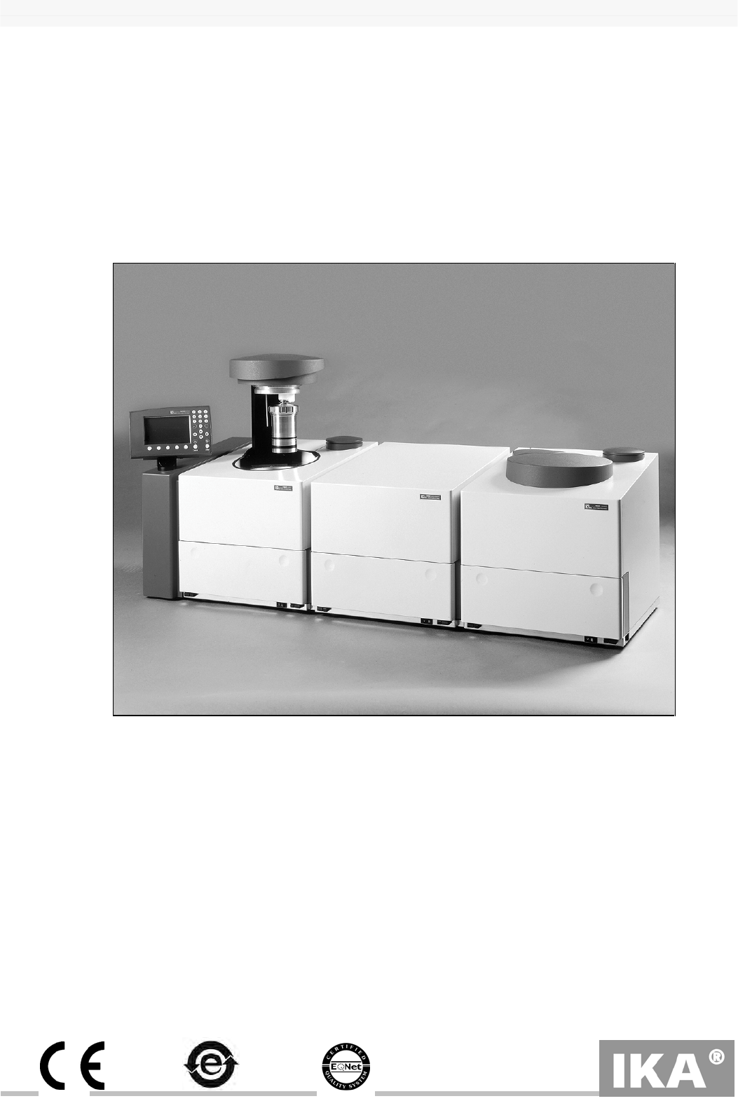
3DJH )HDWXUHV RI WKH V\VWHP The & FRQWURO and & GXR FRQWURO calorimeter systems are used for routine determinations of the gross calorific value of solid and liquid substances. The two systems conform to all gross calorific value standards in accepted use, and are thus recognized worldwide. The extensive selection of accessories and the modular design of the systems ensure customized adaptation to laboratory tasks.
IKA-WERKE C 5000 control/duo-control Ver. 10 04.
5-1 3DJH 7UDQVSRUWDWLRQ VWRUDJH DQG VHWXS ORFDWLRQ &RQGLWLRQV IRU WUDQVSRUWDWLRQ DQG VWRUDJH The system must be protected from mechanical bumps, vibrations, accumulations of dust and corrosive ambient air during transportation and storage. It is also important to observe that the relative humidity not exceed 80%. In case of repair the device has to be cleaned and free from any materials which may constitute a health hazard.
IKA-WERKE C 5000 control/duo-control Ver. 10 04.
3DJH 8QSDFNLQJ Please unpack the unit carefully and make note of any damages. It is important that any damage that occurred during shipping be noted at once while unpacking. If damage has occurred, you should take stock of this damage immediately (noting whether by mail, rail or express delivery, etc.). The following sections describe the entire range of components included with delivery, including the various system variants.
IKA-WERKE C 5000 control/duo-control Ver. 10 04.
3DJH 'HVFULSWLRQ RI WKH V\VWHP FRPSRQHQWV &RQWUROOHU ZLWK PHDVXUHPHQW FHOO Together with the measurement cell, the controller makes up the core of the calorimeter system. The controller works as a central control, interface and display unit for all system components. Operating commands and experiment parameters can be entered through the control console (see the following illustration).
'HVFULSWLRQ RI WKH V\VWHP FRPSRQHQWV 3DJH &RQWUROOHU device connections The individual tasks performed by the controller are as follow: • Dialog with the user through the control console • Store experiment data and experiment protocols ordered by experiment, experiment documentation • Perform experiments automatically, control and monitoring of measurement cell(s) • Communication with the peripheral devices: Printer, analytical scale, sample rack, external PC IKA-WERKE C 5000 control/duo-
3DJH 0HDVXUHPHQW FHOO The combustion of fuel samples takes place in the measurement cell under precisely defined conditions.
'HVFULSWLRQ RI WKH V\VWHP FRPSRQHQWV 3DJH 0HDVXUHPHQW FHOO FRPSRQHQWV In order to achieve these experiment conditions, the following components are housed in the measurement cell • Inner vessel with a water jacket • Magnetic stirrer to create even distribution of heat within the inner vessel • A water system with pump, expansion container and connection for an external cooling unit • Heater and temperature controller • O2 filling and degassing device The measurement cell receives the signa
3DJH IKA-WERKE C 5000 control/duo-control Ver. 10 04.
'HVFULSWLRQ RI WKH V\VWHP FRPSRQHQWV 3DJH 6\VWHP FRPSRQHQWV SHULSKHUDO GHYLFHV With the maximum number of components included and attached, the calorimeter system includes the following components: System components: Measurement cell 1 with controller Measurement cell 2 C 5002 cooling system Peripheral devices: Printer Analytical scale C 5020 sample rack ! System components and peripheral devices with maximum number of components IKA-WERKE C 5000 control/duo
3DJH & FRROLQJ V\VWHP " # $ The C 5002 cooling system cools the water systems of the two measurement cells. One heat exchanger takes care of the cooling required for each circuit. A compressor with a liquifier and an evaporator generates sufficient cooling output for two measurement cells of the C 5000 calorimeter system. The ventilator takes in cool air through the bottom of the unit to draw off the heat it generates.
'HVFULSWLRQ RI WKH V\VWHP FRPSRQHQWV 3DJH & FRROLQJ V\VWHP %& # $ The C 5001 cooling system cools the water systems of one measurement cell. One heat exchanger takes care of the cooling required for the circuit. A compressor with a liquifier and an evaporator generates sufficient cooling output for the measurement cell of the C 5000 calorimeter system.
3DJH & FRROLQJ V\VWHP $'( # $ The C 5004 cooling system cools the water system with one measurement cell. The secondary circuit of the system is connected to an external water supply to divert heat. Please observe the operating instructions C 5004. IKA-WERKE C 5000 control/duo-control Ver. 10 04.
IKA-WERKE C 5000 control/duo-control Ver. 10 04.
3DJH 6HWWLQJ XS DQG SODFLQJ LQ VHUYLFH The components of the C 5000 calorimeter system are unpacked and are located at the place where you will set them up (see Section 5, paragraph 5.2 on the location for setting up the unit). Open the front flap of the measurement cell or of the two measurement cells for the C 5000 duo-control by pushing on both recesses at the same time. Then carry out each of the following steps: IKA-WERKE C 5000 control/duo-control Ver.
6HWWLQJ XS DQG SODFLQJ LQ VHUYLFH 3DJH 6HWWLQJ XS SDFNDJH c Install the ventilation hose according to the following illustration: ! " # $ % & The combustion gasses are discharged through the ventilation hose after each combustion experiment. The ventilation hose should not be squeezed or kinked while the hose is being laid.
3DJH d Screw the pressure hose (O2 line) with the M8x1 cap screw onto the oxygen connection sleeve of the measurement cell with an open-ended spanner (opening 10, included with delivery), and install the hose according to the following illustration: * ! ! " # $ % & e Using the handle (included with delivery of the decomposition vessel), remove the blind plugs from the cold water connections of the
6HWWLQJ XS DQG SODFLQJ LQ VHUYLFH 3DJH f Make sure that the oxygen supply line is connected to the C 5000 calorimeter as described under Point d. Then connect the O2 line to the laboratory oxygen supply end. Please refer to chapter 8.4 for details how to connect to oxygen supplies. The oxygen supply line supplied is suitable for a pressure of max. 40 bar. It is 2 m long, and the smallest permissible bending radius is 80 mm.
3DJH 6HWWLQJ XS SDFNDJH For Package 2, setting up the measuring cell and connecting the oxygen supply are identical to the procedures for Package 1. Please carry out Points c to f as described in Section 8.1 “Setting up package 1“, and then continue with Point g of this Section (8.2). g Place the C 5004 cooling system on the water connection of the measurement cell: + , ,-/.
6HWWLQJ XS DQG SODFLQJ LQ VHUYLFH 3DJH 6HWWLQJ XS SDFNDJH c Open the front flaps of both measurement cells and install the ventilation hose according to the following illustration: , ! $ ( ( $ 6 ! " # $ % & The combustion gasses are discharged through the ventilation hose after each combustion experiment.
3DJH d Assemble the basic unit, the C 5002 cooling system and the second measurement cell together as illustrated in the following illustration: 7 ( # 8 ( ( $ 9$ ! : e Screw the pressure hose with the two M8x1 cap screws onto the oxygen connection sleeves of the measurement cells (with an SW10 open-ended spanner, included with delivery). 7 ( # IKA-WERKE C 5000 control/duo-control Ver.
6HWWLQJ XS DQG SODFLQJ LQ VHUYLFH 3DJH f Connect the second measurement cell with the controller through the extension cord. The plugs should be screwed in place. 7 ( # , ; $ ! g Remove the blind plugs and insert the water hoses into the water hose connections of the cooling system and the two measurement cells (see Section 8.1, Part 3). 7 ( # , " h Set the pivot plates in place.
3DJH &RQQHFWLRQ R[\JHQ VXSSO\ Installation The 2 m long O2 hose supplied with the system is designed for a maximum pressure of 40 bar at room temperature. This can either be fed directly to the oxygen cylinder or to another oxygen connection point with a pressure reducer (smallest permitted bending radius 80 mm). The C 29 reducer valve (accessory) for the oxygen cylinder features an R ¼ inch thread for connecting the pressure hose.
6HWWLQJ XS DQG SODFLQJ LQ VHUYLFH 3DJH &RQQHFWLQJ SHULSKHUDO GHYLFHV If sample racks, electronic scale or a printer have been delivered with the calorimeter, they should be connected now. The connection sockets are located on the rear wall of the controller. When connecting the sample rack, take note of the labeling for the connection cable.
3DJH )LOOLQJ WKH V\VWHP FLUFXLW c The liquid with which the system is filled must be prepared as follows (about 5 liters per measurement cell): • • • • Fill a clean container with about 2.5 liters of distilled water Add 5 ml of Aqua-Pro Add the remaining 2.5 liters of distilled water to the container Stir the mixture, or close the container and shake A clean container that can be grasped easily should be used to fill up the system circuit with liquid.
6HWWLQJ XS DQG SODFLQJ LQ VHUYLFH 3DJH $ Because there is only a small amount of water in the expansion container, the following message now appears: 5HILOO ZLWK ZDWHU RU HPSW\ ,9 (IV - inner vessel) At the same time, an acoustic signal is heard. This message must be ignored at first, and you PXVW QRW confirm it by pressing the 2. key. A B ) ( IKA-WERKE C 5000 control/duo-control Ver. 10 04.
3DJH Now pour in about 1-1.5 liters (in any case, enough for the message on the display and the signal to go off) of WKH SUHSDUHG PL[WXUH evenly and slowly. This will turn the pump on automatically and the water will be pumped from the expansion container into the system. As the water level in the expansion container sinks, the same message appears again: 5HILOO ZDWHU RU HPSW\ ,9 and the acoustic signal is heard. This message must be ignored again, and you PXVW QRW confirm it by pressing the 2. key.
6HWWLQJ XS DQG SODFLQJ LQ VHUYLFH 3DJH f Continue filling with the prepared liquid until the message on the display goes off. The water capacity in the entire system is about 4.5 liters. Set the cover back on the expansion container with a turning motion. The rest of the mixture will be required later on for operating the unit.
3DJH &RQWURO DQG GLVSOD\ HOHPHQWV Before you continue with the next steps in preparing the system for operation, you should become familiar with the display and control console. The control console is equipped with the following elements: -> 1. 2. 3 4. 5. 6. ☞ /& GLVSOD\ for showing system data, experiment data as well as menus and dialog boxes for entering data.
6HWWLQJ XS DQG SODFLQJ LQ VHUYLFH 3DJH 7 8. 9. 10. /HIW ULJKW XS DQG GRZQ DUURZ NH\ The arrow keys move the cursor within the entry lines, menu windows, tables and protocols. 1XPEHU EORFN You can enter numbers, decimal points and blank spaces with these keys. You can open up or close an additional information window for service purposes with the decimal key outside of a dialog box. You can print out the content of this window with the space bar .
3DJH C ; (: ! ," " $FWLYH GLDORJ HOHPHQW (QWU\ OLQH All dialog elements are labeled. Active dialog elements are identified by the character ª. You can cycle through and make each element in turn the active element by repeatedly pressing 7$% Only the active dialog element can be accessed (have some function performed on it). The button is an exception to this rule. Digits and decimal points can be entered in an active entry line.
6HWWLQJ XS DQG SODFLQJ LQ VHUYLFH 3DJH 7XUQLQJ RQ WKH V\VWHP When you turn on the calorimeter system (measurement and cooler), the opening screen first appears (the cover of the measurement cell opens up automatically). $ In the footer line you can see the current assignment of the function keys. You must confirm the opening screen with the 2. key to reach the main screen. D 8 $ You can reach all menu and dialog windows from the main screen.
3DJH D 8 $ 8" $6 ) ( You can move the cursor through menu lines with the arrow keys. You can also open a menu window with $UURZ GRZQ or 2., and then a dialog box with 2. D 8 $ 8" $6 ) :( " " If the error message 5HILOO ZDWHU RU HPSW\ ,9 (IV = inner vessel appears while you are confirming the opening screen, check to see the water level of the inner vessel (visual check).
6HWWLQJ XS DQG SODFLQJ LQ VHUYLFH 3DJH If the error message is not eliminated in spite of the inner vessel being emptied, you must pour 50 ml of the prepared liquid into the expansion container. The message then disappears. If this quantity alone is not sufficient, then repeat the last step in 50-ml increments.
3DJH Meaning of the entries:
6HWWLQJ XS DQG SODFLQJ LQ VHUYLFH 3DJH 6\VWHP VHWWLQJV A few system settings must still be made for the experiment procedure, the method of working, the initialization of the experiment, the reference gross calorific value and the unit of measure for the gross calorific value. To do this, place the cursor in the menu line on &RQI , open the menu window and call up the 6HWWLQJV dialog box. P I H H L Q R S # ; The window shows the configuration boxes of the calorimeter.
3DJH > @ 8VHU GHI QDPH Here you can specify whether you will enter the 6DPSOH name yourself in the 6DPSOH QDPH configuration box and in the 6DPSOH dialog box, or whether the system will automatically assign the 6DPSOH QDPH. If you do not select this option, the system assigns experiment numbers in the 6DPSOH QDPH box. > @ 2 ULQVLQJ With this option, the decomposition vessel is briefly filled with oxygen, after which the oxygen is released each time, before the actual filling with oxygen.
6HWWLQJ XS DQG SODFLQJ LQ VHUYLFH 3DJH /DVW H[SHULP The system accepts the 8VHU and 6DPSOH SURSHUWLHV parameters for a new experiment as well as the indicated post-experiment parameters of the last experiment to be evaluated. If the 8VHU GHI QDPH option has been selected, the sample name is also accepted. This must then be edited or reentered to make up for the difference. 6WDQGDUG The post-experiment parameters are set to 0 for a new experiment.
3DJH &RQILJXULQJ WKH VFDOH If electronic scale is attached to the system, the scale type must be configured. To do this, open the 6FDOH dialog box in the &RQI menu box. P=T F U I # ; The window displays the configuration of the scale. The parameters you select here must agree with the interface parameters of the attached scale. Please refer to the scale manual for the parameters.
6HWWLQJ XS DQG SODFLQJ LQ VHUYLFH 3DJH :LWK FRPEXVWLRQ DLG configuration box If the option :LWK FRPEXVWLRQ DLG is marked, the values of the scale are transferred in the following order: 1. “Weighed in combustion aid” 2. “Weighed in combustion aid + weighed in sample” 5HYHUVH configuration box If the box UHYHUVH is marked in addition to the configuration box :LWK FRP EXVWLRQ DLG scale values will be transferred in the following order: 1. “Weighed in sample” 2.
3DJH 6\VWHP FDOLEUDWLRQ Before it is possible to make precise measurements with the calorimeter system, it must be calibrated. This is done by burning tablets of FHUWLILHG EHQ]RLF DFLG (see accessories) with a known gross calorific value. This makes it possible to determine the heat capacity (the C value) of the system based on the amount of heat that is required to raise the temperature of the calorimeter system by 1 degree Kelvin.
6\VWHP FDOLEUDWLRQ 3DJH &KDUJLQJ WKH GHFRPSRVLWLRQ YHVVHO ZLWK WKH FDOLEUDWLRQ VXEVWDQFH 7KH LQVWUXFWLRQV LQ FKDSWHU ³)RU \RXU 6DIHW\´ PXVW EH IROORZHG For further details please see the operating instructions of the decomposition vessels C 5010 and C 5012.
3DJH ☞ ,I PRUH WKDQ RQH GHFRPSRVLWLRQ YHVVHO LV EHLQJ XVHG WKH UHVSHFWLYH LQGLYLG XDO SDUWV PXVW QRW EH H[FKDQJHG EHWZHHQ WKH YDULRXV GHFRPSRVLWLRQ YHVVHOV VHH WKH HQJUDYLQJ RQ WKH LQGLYLGXDO SDUWV On cleaning the decomposition vessel, see Section 10.4 To prepare the coded decomposition vessel, follow the steps listed below: c Screw off the cap screw and take off the cover with the aid of the handle.
6\VWHP FDOLEUDWLRQ 3DJH f Make certain that the desired operating mode (isoperibolic, adiabatic, or dynamic) is set (see Section 8.8 “Configuring the system”). Open the 6DPSOH dialog window to enter parameters. If a sample rack is active, parameter input is opened automatically by setting or removing a crucible (see also C 5020 Operating Instructions). ) * +", - .$ & / Enter the weight of the combustion sample in the :HLJKHG LQ TXDQWLW\ box.
3DJH 1RWH In all automatic calculations, 70 J is taken into account for the electrical ignition energy. 6DPSOH QDPH The software automatically assigns a sample number for each measurement of the format \PPGGQQ, where \ is the year, PP is the month, GG the day and QQ a running number. It is easy with sample numbers formed in this manner to select and work with specific groups of measurements from the library.
6\VWHP FDOLEUDWLRQ 3DJH i Place the crucible in the crucible holder. % " ' ( ! j Attach cotton thread The decomposition vessel is fitted with a permanent ignition wire. In order to initiate the combustion process, a cotton thread must be attached to the ignition wire. Attach the cotton thread as shown in the illustration. Align the cotton thread with a pair of tweezers so that it is suspended into the crucible and touches the sample.
3DJH &DOLEUDWLRQ c Guide the decomposition vessel carefully until it interlocks with the filling head of the open measurement cover (No. 1 in the following illustration) $OZD\V KROG WKH GHFRPSRVLWLRQ YHVVHO E\ WKH WRS RI WKH FDS VFUHZ The decomposition vessel maintains a defined position in the holder on the fill head by being lowered at the centre of the fill head by 0.8 mm (no. 2 in the following illustration).
6\VWHP FDOLEUDWLRQ 3DJH d Activate 6WDUW. The measurement cell cover closes. Each time 1000 ignitions have been performed using a given decomposition vessel, the following message will appear: 1000 ignitions performed with Bomb x Inspect decomposition vessel or contact IKA service This indicates that the decomposition vessel has reached a maintenance point and that a safety check must be carried out. Confirm this message by pressing 7$% and 2. in sequence.
3DJH h Open the decomposition vessel and check the crucible for any signs of incomplete combustion. If combustion was not complete, the results of the experiment must not be used for calibration. The experiment must be repeated. i Clean the decomposition vessel as described in Section 10.4 (or the Operating Instructions for decomposition vessel C 5010/C 5012) and prepare the next experiment. j Perform a number of calibration experiments for each decomposition vessel as described in Section 9.
6\VWHP FDOLEUDWLRQ 3DJH cc Open the &DO dialog box. 5@* - A > : 2& / Using the button &DOF in the FDOLE dialog box, carries out the acid correction for the selected calibration. The calculation is dependent on the evaluation procedure selected: • Evaluation procedure ASTM D1989, D240, D5865, D4809, D5468, E711 For calibration, a dialog reduced to the acid-correction fields and a shortened results form are displayed. The comments in Section 11.2 under Point } apply here too.
3DJH ce Using the 7DE key and the 'RZQ DUURZ key, place the cursor on the next experiment and activate 6HO. With this, you have selected the next experiment for calibration. The average value of the selected experiments, the average, relative error as a percentage, as well as the scattering range (max-min) absolutely and as a percentage are displayed in the corresponding boxes.
3DJH 'HWHUPLQLQJ JURVV FDORULILF YDOXHV 'HFRPSRVLWLRQ YHVVHOV & DQG & DUH QRW SHUPLWWHG IRU H[SHULPHQWV RQ IXHO VDPSOHV FDSDEOH RI H[SORGLQJ 1RWH LQ WKLV UHJDUG &KDSWHU ³)RU \RXU VDIHW\´ 7KH LQGLYLGXDO SDUWV DQG LQ SDUWLFXODU WKH WKUHDGLQJ RI WKH GHFRPSRVLWLRQ YHV VHO PXVW EH FKHFNHG UHJXODUO\ IRU ZHDU DQG FRUURVLRQ 1RWH LQ WKLV UHJDUG 2S HUDWLQJ ,QVWUXFWLRQV & RU & The C 5000 calorimeter system is a precision measuring instrument for routine determinations of g
'HWHUPLQLQJ JURVV FDORULILF YDOXHV 3DJH &RPEXVWLRQ DLG The capsules described above, or combustion bags made of polyethylene (see accessories) can also be used as combustion aids for substances with low inflammability or low-calorific substances. The combustible crucible C 14 can also be used.
3DJH 3URFHGXUH IRU GHWHUPLQLQJ JURVV FDORULILF YDOXH After the system has been switched on and you have acknowledged the opening screen with 2., it requires about 30 minutes until the stable temperature conditions are prevalent in the measurement cell. Before a measurement is started, the system must have previously been calibrated as described in Section 9 “Calibration”. c The decomposition vessel must be clean and dry. See item 10.4.
'HWHUPLQLQJ JURVV FDORULILF YDOXHV 3DJH d Suspend carefully the decomposition vessel into the open measurement cell cover until it reaches the stopper (1., see the following illustration). $OZD\V KROG WKH GHFRPSRVLWLRQ YHVVHO E\ WKH WRS RI WKH FDS VFUHZ The decomposition vessel maintains a defined position in the holder on the fill head by being lowered at the centre of the fill head by 0.8 mm (no. 2 in the following illustration).
3DJH e Activate 6WDUW. The measurement cell cover closes. Each time 1000 ignitions have been performed using a given decomposition vessel, the following message will appear: 1000 ignitions performed with Bomb x Inspect decomposition vessel or contact IKA service This indicates that the decomposition vessel has reached a maintenance point and that a safety check must be carried out. Confirm this message by pressing 7$% and 2. in sequence.
'HWHUPLQLQJ JURVV FDORULILF YDOXHV 3DJH g The decomposition vessel is vented and the measurement cell cover opens. 8VHU h As soon as the message %RPE n appears, remove the decomposition vessel and open it. i Check the crucible for combustion residue. Both the cotton thread and the fuel sample must have been burned completely. If there are any signs of incomplete combustion, the experiment must be repeated.
3DJH 7XUQLQJ RII WKH V\VWHP ☞ ☞ If you want to turn off the calorimeter system, open the 6\VWHP menu and call ([LW For a duo-control system, measurement cell No. 2 can be turned off separately. 1R GHFRPSRVLWLRQ YHVVHO PXVW EH VXVSHQGHG LQ WKH PHDVXUHPHQW FHOO FRYHU If you are working with a duo-control system, you must activate the display for measurement cell No. 1 with 7DE ([LW then turns off the entire system. If the display for measurement cell No. 2 is active, only measurement cell No.
IKA-WERKE C 5000 control/duo-control Ver. 10 04.
3DJH (YDOXDWLQJ H[SHULPHQWV After the determinations of gross calorific value have been completed, you can evaluate the results. In addition to an overview of the experiments, the calorimeter system offers you the possibility of post-processing results and converting them to other references states. You can also print out or delete experiment results. You will find these functions in the menu items (YDOXDWLRQ and /LEUDU\ of the ([SHULPHQWV menu box.
(YDOXDWLQJ H[SHULPHQWV 3DJH +&DO The experiment was performed for calibration purposes. 6LP The experiment was a simulation. (YDO The experiment has been evaluated. – Code Eval: the DIN/IKA evaluation procedure was used. – Code ASTM: the ASTM D1989, D240, D5865, D4809, D5468, E711 evaluation procedure was used. :DLW The fuel sample is in the crucible and all parameters have been entered. The experiment can be started. 3UHS The crucible is in the sample rack with a fuel sample.
3DJH 3RVW SURFHVVLQJ H[SHULPHQWV IURP WKH OLEUDU\ c Open the Library dialog box in the Experiments menu box. The header indicates the number of experiments still available in memory. ! " # $ % d A search mask appears into which you must enter the sample name of the experiment that you would like to post-process.
(YDOXDWLQJ H[SHULPHQWV 3DJH $& $ $ # $ $ # $' % e A list of experiments appears whose sample name matches the search mask.
3DJH d A list appears with the daily experiments. Use the 8S DUURZ 'RZQ DUURZ keys to select the appropriate experiment and press the key or place the cursor on the &DOF button with 7DE and confirm with 2. ( ) ( )* # * + ! e There are two different windows, which one is used depends on the evaluation procedure: 1.
(YDOXDWLQJ H[SHULPHQWV 3DJH Dialog box for ,.-0/ 1" 2 1 # *3 4*5 1 # *3 6 5 IKA-WERKE C 5000 control/duo-control Ver. 10 04.
3DJH 1 # *3 8 5 2. Evaluation procedure DIN/IKA A dialog box opens for entering the results of analytical examination of the sample and combustion residues. Parameters that have been determined in the supply state of the sample are designated with (raw) and parameters from the reference state analysis moist with (an). In the dialog box you will find the entry boxes for the parameters of the selected calculation mode.
(YDOXDWLQJ H[SHULPHQWV 3DJH %D 2+ 7 The titrated quantity of 0.1 N barium hydroxide (titration of the distilled water with which the decomposition vessel was rinsed out after the experiment). 1D 7 &2 9 Quantity of sodium carbonate that was present in the decom position vessel (20 ml according to DIN specification; 0.05 N). +&O The titrated quantity of 0.1 N hydrochloric acid (titration of the distilled water with which the decomposition vessel was rinsed out after the experiment).
3DJH %D 2+ 7 The titrated quantity of 0.1 N barium hydroxide (titration of the distilled water with which the decomposition vessel was rinsed out after the experiment). 1D 7 &2 9 Quantity of sodium carbonate that was present in the decomposition vessel (20 ml, 0.05 N). +&O The titrated quantity of 0.1 N hydrochloric acid (titration of the distilled water with which the decomposition vessel was rinsed out after the experiment). 5RXJK PRLVW UDZ The percentage of water from rough moisture.
(YDOXDWLQJ H[SHULPHQWV 3DJH %D 2+ 7 The titrated quantity of 0.1 N barium hydroxide (titration of the distilled water with which the decomposition vessel was rinsed out after the experiment). 1D 7 &2 9 Quantity of sodium carbonate that was present in the decomposition vessel (20 ml, 0.05 N). +&O The titrated quantity of 0.1 N hydrochloric acid (titration of the distilled water with which the decomposition vessel was rinsed out after the experiment).
3DJH 5RXJK PRLVW UDZ The percentage of water from rough moisture. $VK DQ The percentage of ash. +\JU PRLVW DQ The percentage of water from hygroscopic moisture. 1D2+ The titrated quantity in ml (0.0866 N). 6XOIXU DQ The percentage of sulfur. f Enter the required parameters for the calculation mode selected and confirm the dialog box after the last entry with 2.
(YDOXDWLQJ H[SHULPHQWV 3DJH g A new window appears and shows the measurement protocol with the definitive results of the experiment. You can print the measurement protocol by pressing the space bar and close the window with 2.. You can scroll through the protocol with the arrow keys. Meaning of the individual correction parameters: + 7 2 HOHPHQWDU\ DQDO\VLV The percentage of water in the fuel sample, as determined by elementary analysis.
3DJH 1D 7 &2 9 SUHVHQW The quantity of Na2CO3 present in the decomposition vessel. 4 VXOIXU The heat of solution from the formation of sulfuric acid. 4 QLWURJHQ The heat of solution from the formation of nitric acid. +R UDZ The specific gross calorific value of the fuel sample in the supply state. +R DQ The specific gross calorific value of the fuel sample in the “analysis moist” reference state.
IKA-WERKE C 5000 control/duo-control Ver. 10 04.
3DJH ([SHULPHQW VLPXODWLRQ In many cases it is helpful to perform gross calorific value experiments or to calculate possible experiment results without actually performing the combustion experiment. Using the 6LPXODWLRQ dialog box in the ([SHULPHQWV menu box, the calorimeter system simulates experiments on the basis of data that is provided. This option is especially useful if a calibration was unintentionally performed instead of a determination of a gross calorific value or vice-versa.
([SHULPHQW VLPXODWLRQ 3DJH e As soon you have confirmed the data with 2., a dialog box appears for entering the simulation parameters. "!" #%$" & ' ( #*)& ) ! f You must enter the following parameters: & YDOXH 7HPS'LII Heat capacity of the calorimeter system The temperature difference at which the simulated combustion is conducted. g Confirm the dialog box with 2..
3DJH &DUH DQG PDLQWHQDQFH In order to ensure problem-free operation over a long time, the following maintenance tasks should be performed on the calorimeter system: 6LHYH LQVHUW &KHFN WKH VLHYH LQVHUW GDLO\ ZKLOH UHILOOLQJ WKH SUHSDUHG OLTXLG The entire volume of water in the system is constantly circulated and kept free of impurities by the sieve insert in the filling sleeve of the expansion container.
&DUH DQG PDLQWHQDQFH 3DJH During routine operation, liquid is removed from the system through evaporation and by adhering to the decomposition vessel. If this error message appears on the display during normal operation: 5HILOO ZLWK ZDWHU RU HPSW\ ,9 LQQHU YHVVHO you should add 50 ml of the mixture to the expansion container. If the message on the display does not go away, repeat the refilling process in increments of 50 ml.
3DJH d Have a container with a capacity of at least 5 l ready, and lead the water outlet hose into it. Alternatively, you can lead the outlet hose into a drain or sink. As soon as you push the water drain hose into the water drain connection, the cooling water system empties itself. Push on the locking button of the water drain connection to insert and remove the hose.
&DUH DQG PDLQWHQDQFH 3DJH 5HSODFLQJ WKH LQQHU FRYHU 2 ILOOLQJ SLVWRQ If it should become necessary to break down the inner cover to replace parts, it can be put back together again as shown in the following illustration. ! " # $ 6SDUH SDUWV OLVW ,WHP 3LHFHV 1DPH Capillary cpl. Piston cpl.
3DJH If it should become necessary to replace the O2 filling piston (item 2), proceed as follows: c Loosen the screws (item 6) with a blade-screwdriver. d Remove the centering ring (item 7) together with the filling head (item 5), the pressure spring (item 3) and the piston (item 2) Caution: The seals (item 4 and item 8) are free e Push the pressure spring (item 3) onto the new piston and insert both parts into the filling head. The remainder of the assembly takes place in the opposite order.
IKA-WERKE C 5000 control/duo-control Ver. 10 04.
3DJH 7URXEOHVKRRWLQJ The C 5000 calorimeter system is subject to strict quality control during manufacturing. If improper functionality should nevertheless occur, you will find a series of malfunction situations with the appropriate measures for eliminating the problem. Most malfunctions are displayed in the header line of the display. Alternatively or in addition, a message box may appear which the user must acknowledge.
7URXEOHVKRRWLQJ 3DJH 2 VHDO The piston on the oxygen filling unit in the measurement cell cover is extended and then retracted again when it is activated a second time. 2 )LOO A decomposition vessel that is suspended in the measurement cell cover is filled with oxygen. The process ends after about 50 seconds. The process is displayed in the process window. During this procedure, the decomposition vessel cannot be removed.
3DJH • 1R LQFUHDVH LQ WHPSHUDWXUH DIWHU HOHFWULFDO LJQLWLRQ 0HVVDJHV RQ WKH GLVSOD\ 1R LQFUHDVH LQ WHPSHUDWXUH The system displays the malfunction and interrupts the measurement. Check the ignition wire, the cotton thread, the fuel sample and the O2 supply. It may be that you will have to use a combustion aid.
7URXEOHVKRRWLQJ 3DJH • 7HPSHUDWXUH FRQWURO RI WKH V\VWHP XQVWDEOH 0HVVDJHV RQ WKH GLVSOD\ ³8QVWDEOH´ VWDWXV The “unstable” condition may last up to 10 minutes after turning on the machine, and up to 5 minutes between measurements. If this time is exceeded significantly, or if the “stable” condition is no longer reached at all, select the 5HVHW option from the PDLQWHQDQFH menu. Check in addition the functionality of the cooler (make sure hot air is coming out of the outlet).
3DJH • ,QFRPSOHWH FRPEXVWLRQ Check the O2 supply to the unit (30 bar). Use a combustion aid if necessary (see also the applicable standards under ”Taking samples/sample preparation”. • &RYHU FDQQRW EH UHPRYHG IURP WKH GHFRPSRVLWLRQ YHVVHO The O2 filling / ventilation procedure is still running (see the status window in the display).
7URXEOHVKRRWLQJ 3DJH 3HUIRUPLQJ DQ DGMXVWPHQW DGLDEDWLF PRGH If the unit is going to be operated in adiabatic mode, an adjustment is required first. This has already been performed at the factory during the functional test. Under normal laboratory conditions, the user must perform an adjustment again if: • Measurement times for adiabatic measurements regularly take longer than 25 minutes.
3DJH $FFHVVRULHV DQG &RQVXPDEOHV $FFHVVRULHV 2UGHULQJ GHVFULSWLRQ C 5010 C 5012 C 5010.4 C 5010.5 C 5010.6 C 5020 C 5030 C 5040 C 21 C 29 KV 600 IKA decomposition vessel, standard IKA decomposition vessel, halogen resistant Holding surface for disposable crucible Holding surface large crucible Venting button Sample rack Venting station CalWin, calorimeter software Pelleting press Reduction valve Cooler unit &RQVXPDEOHV 2UGHULQJ GHVFULSWLRQ C 710.4 C 5010.3 C 5012.3 C 5003.
IKA-WERKE C 5000 control/duo-control Ver. 10 04.
3DJH 7HFKQLFDO GDWD 7HFKQLFDO GDWD IRU WKH FRQWUROOHU Operating power Power consumption: C 5000 control (controller with one measurement cell) C 5000 duo-control (controller with two measurement cells) Device fuses Protection type according to DIN 40 050 Protection class Over-voltage category Contamination level Ambient temperature Ambient relative humidity Dimensions (Controller with measurement cell, without display) Weight (controller with measurement cell) Display electrical power is su
7HFKQLFDO GDWD 3DJH 7HFKQLFDO GDWD IRU WKH & FRROLQJ V\VWHP Operating power Power consumption Cooling output Device fuses Protection type according to DIN 40 050 Protection class Over-voltage category Contamination level Ambient temperature Ambient relative humidity Dimensions Weight see rating plate max. 300 Watts 240 Watts 2 x 3.0 A, FF; 230 V 2 x 6.0 A, FF; 100/115 V IP 21 1 (protective grounding) 2 II 15°C ...
3DJH %DVLF FDOFXODWLRQV The following sections list mathematical formulas that are used to calculate results of measurements. The calorimeter system acquires the data required for the measurements partially during the combustion process and the data is partially the results of analyses of examination on fuel samples or on combustion products. The calculations correspond to the applicable standards (DIN 51900, ASTM 240D, ISO 1928, BSI) for gross calorific values and net calorific values.
%DVLF FDOFXODWLRQV 3DJH ³6WDQGDUG ZLWKRXW WLWUDWLRQ´ PRGH 1HW FDORULILF YDOXH RI WKH IXHO VDPSOH HUan = HOan − (H2 O ⋅ 24.41) (QHUJ\ IURP WKH IRUPDWLRQ RI VXOIXULF DFLG Q S = S an ⋅ m ⋅ 94.62 (QHUJ\ IURP WKH IRUPDWLRQ RI QLWULF DFLG QN = Nan ⋅ m⋅ 43 ³6WDQGDUG ZLWK WLWUDWLRQ´ PRGH 3HUFHQWDJH RI VXOIXU S an = QS m ⋅ 94.62 (QHUJ\ IURP WKH IRUPDWLRQ RI VXOIXULF DFLG Q S = 15.
3DJH ³&DUERQ + LQSXW ZLWKRXW WLWUDWLRQ´ PRGH &RQYHUVLRQ IDFWRU IURP UHIHUHQFH VWDWH DQ WR UDZ F1 = 100 − H2 O raw 100 − hFan 3HUFHQWDJH RI VXOIXU S raw = S an ⋅ F1 3HUFHQWDJH RI ZDWHU H2 O raw = gFraw + hFraw 3HUFHQWDJH RI DVK A raw = F1 ⋅ A an +\JURVFRSLF PRLVWXUH hFraw = F1 ⋅ hFan 3HUFHQWDJH RI K\GURJHQ H2raw = F1 ⋅ H2an H 2 waf = H 2an ⋅ 100 100 − (Aan + hF an ) 9RODWLOH FRPSRQHQWV fB raw = 100 − (H2 O raw + A raw ) ⋅ fB waf 100 H2 O raw = gFraw + hFan fB an = fB raw F1 IK
%DVLF FDOFXODWLRQV 3DJH fB waf = 0.115 − 0.115 2 − 4[(H2 waf − 2.98 )⋅ 0.00142] 0.00284 Remark: This approximation formula applies for mineral coal with a percentage of volatile components between 6% and 40%. (QHUJ\ IURP WKH IRUPDWLRQ RI VXOIXULF DFLG Q S = S an ⋅ m ⋅ 94.
3DJH ³&DUERQ + LQSXW ZLWK WLWUDWLRQ´ PRGH &RQYHUVLRQ IDFWRU IURP UHIHUHQFH VWDWH DQ WR UDZ F1 = 100 − H2 O raw 100 − hFan 3HUFHQWDJH RI VXOIXU S an = QS m ⋅ 94.
%DVLF FDOFXODWLRQV 3DJH fB waf = 0.115 − 0.115 2 − 4[(H2 waf − 2.98 )⋅ 0.00142] 0.00284 Remark: This approximation formula applies for mineral coal with a percentage of volatile components between 6% and 40%. (QHUJ\ IURP WKH IRUPDWLRQ RI VXOIXULF DFLG Q S = 15.
3DJH ³&DUERQ YRODWLOH LQSXW ZLWKRXW WLWUDWLRQ´ PRGH &RQYHUVLRQ IDFWRU IURP UHIHUHQFH VWDWH DQ WR UDZ F1 = 100 − H2 O raw 100 − hFan 3HUFHQWDJH RI VXOIXU S raw = S an ⋅ F1 3HUFHQWDJH RI ZDWHU H2 O raw = gFraw + hFraw 3HUFHQWDJH RI DVK A raw = F1 ⋅ A an +\JURVFRSLF PRLVWXUH hFraw = F1 ⋅ hFan 3HUFHQWDJH RI K\GURJHQ H2 waf = 2.98 + 0.115 ⋅ fB waf − 0.
%DVLF FDOFXODWLRQV 3DJH (QHUJ\ IURP WKH IRUPDWLRQ RI QLWULF DFLG QN = Nan ⋅ m⋅ 43 *URVV FDORULILF YDOXH RI WKH IXHO VDPSOH HOraw = HOan ⋅ F1 HOan = C⋅ ∆T − QZ − QS m HOwaf = 100 ⋅ 100 − hF an 100 100 100 − Aan ⋅ 100 − hF an ⋅ HOan 1HW FDORULILF YDOXH HUraw = (HUan + 24.41⋅ hFan )⋅ F1 − H2 O raw ⋅ 24.41 HUan = HOan − (H2an ⋅ 218.13 + hFan ⋅ 24.41) HUwaf = (HOraw + 24.
3DJH 3HUFHQWDJH RI ZDWHU H2 O raw = gFraw + hFraw 3HUFHQWDJH RI DVK A raw = F1 ⋅ A an +\JURVFRSLF PRLVWXUH hFraw = F1 ⋅ hFan 3HUFHQWDJH RI K\GURJHQ H2raw = F1 ⋅ H2an H2 waf = 2.98 + 0.115 ⋅ fB waf − 0.00142 ⋅ fB 2waf 9RODWLOH FRPSRQHQWV fB an = fB raw F1 fB waf = fB raw ⋅ 100 100 − (H2 O raw + A raw ) (QHUJ\ IURP WKH IRUPDWLRQ RI QLWULF DFLG QN = 6 ⋅ (Na2 O3 − HCl) (QHUJ\ IURP WKH IRUPDWLRQ RI VXOIXULF DFLG Q S = 15.
%DVLF FDOFXODWLRQV 3DJH *URVV FDORULILF YDOXH RI WKH IXHO VDPSOH HOraw = HOan ⋅ F1 HOan = H Owaf = C⋅ ∆T − ∑ Q m 100 100 − hF an ⋅ 100 100 100 − A an ⋅ 100 − hF an ⋅ H Oan 1HW FDORULILF YDOXH HUraw = (HUan + 24.41⋅ hFan )⋅ F1 − H2 O raw ⋅ 24.41 HUan = HOan − (H2an ⋅ 218.13 + hFan ⋅ 24.41) HUan = HOan − (H2 O ⋅ 24.41) HUwaf = (HOraw + 24.41 ⋅ H 2 O raw )⋅ 100 100 − hFan ⋅ 100 100 100 − A an ⋅ 100 − hFan IKA-WERKE C 5000 control/duo-control Ver. 10 04.
3DJH )RUPXOD V\PEROV Aan Araw Ba(OH)2 C Dx = = = = = F1 fBan fBraw fBwaf gFraw HOan HOB HOraw HOwaf = = = = = = = = = HUan HUraw HUwaf HCl hFan H2an H2raw H2waf H2O = = = = = = = = H2Oraw m Mx MRF MW n Nan Na2CO3 ΣQ = = = = = = = = = QN QS QZ = = = Q1 = San Sraw ∆T = = = Percentage of ash in the reference state analysis moist [%] Percentage of ash in the supply state [%] Titrated quantity 0.
IKA-WERKE C 5000 control/duo-control Ver. 10 04.
3DJH ,QGH[ RI NH\ ZRUGV $ Acetobutyrate capsules ................... 3-4; 10-1 Acid formation ........................................ 10-2 Acid correction.......................................... 3-3 Adiabatic................................................. 8-24 Adjustment ............................................. 8-24 % Benzoic acid ............................................. 3-5 & Calculation modes.................................. 11-6 Calibration experiments ..........................
,QGH[ RI NH\ZRUGV 3DJH 4 Quantity of added substance ................... 9-1 5 Rapidly-burning substances................... 10-1 Reference gross calorific value .............. 8-23 Reference substance ............................... 3-5 6 Scale....................................................... 8-25 Search mask .......................................... 11-3 Simulation............................................... 12-1 Solid materials.................................
IKA-WERKE C 5000 control/duo-control Ver. 10 04.
IKA-WERKE C 5000 control/duo-control Ver. 10 04.