35 488 01 a Calorimeter System C 200 Operating instructions 012011 Reg.-No.
Source language: German EN Contents Chapter Page CE-Declaration of conformity 5 1 Safety instructions 6 2 2.1 2.2 User information Information regarding operating instructions Warranty and liability 8 8 8 3 3.1 3.2 3.3 3.4 Transport, storage, place of installation Conditions of transport and storage Place of installation Unpacking Delivery scope 9 9 9 9 9 4 4.1 4.2 4.3 4.4 4.5 4.6 4.7 4.8 4.9 4.
7 7.1 7.2 Service menue Operation Description of service menue options 26 26 26 8 8.1 8.2 8.3 8.4 8.5 8.6 Cleaning and maintenance Inner vessel filter Filler Micro filter Maintaining the water circulation Decomposition vessels Cleaning informations 27 27 27 27 28 28 28 9 9.1 9.
CE-Declaration of conformity CE – KONFORMITÄTSERKLÄRUNG DE Wir erklären in alleiniger Verantwortung, dass dieses Produkt den Bestimmungen der Richtlinien 89/ 336 EG, 89/ 392 EG und 73/ 23 EG entspricht und mit folgenden Normen und normativen Dokumenten übereinstimmt: EN 61010, EN 50082, EN 55014 und EN 60555.
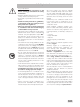
1 Safety instructions For your protection • Read the operating instructions in full before starting up and follow the safety instructions. • Keep the operating instructions in a place where they can be accessed by everyone. • Ensure that only trained staff work with the appliance. • Follow the safety instructions, guidelines, occupational health and safety and accident prevention regulations. • Wear your personal protective equipment in accordance with the hazard category of the medium to be processed.
with test pressure of 330 bar and a leakage test with oxygen at 30 bar. • Decomposition vessels are experiment autoclaves and must be tested by a technical expert after each use. Individual use is understood here to include a series of experiments performed under roughly the same conditions in terms of pressure and temperature. Experiment autoclaves must be operated in special chambers (C 2000, C 5000, C 7000, C 200).
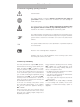
2 User information 2.1 Information regarding operating instructions General hazard This symbol indicates information which is essential for the safety of your health. Failure to observe this information can cause damage to health and injuries. This symbol indicates information which is important for ensuring that the appliance functions without any technical problems. Failure to observe this information could damage the calorimeter system.
3 Transport, storage, place of installation 3.1 Conditions of transport and storage • The system must be protected against mechanical impact, vibrations, dust deposits and corrosive ambient air during transportation and storage. • It is also important to ensure that the relative humidity does not exceed 80%. • Only the original packing may be used for transportation. • The appliance must be completely emptied before storing and transportation. 3.
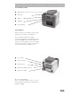
4 Installation and starting up 4.1 Calorimeter C 200 Measuring cell cover Tank fillers Display Keyboard Fill level display 4.2 Installation All the connections for draining as well as the peripherals are on the back of the appliance. Connecting the table power supply Connect the calorimeter to the table power supply (4-pin plug ). Check that the voltage information on the rating plate of the power supply unit matches your mains supply.
Connecting the water drain Inner vessel emergency drain Tank drain Inner vessel drain TIP Insert the emptying hose (included in package contents) into plug-in coupling . Place this in the mould so that it is sloping. This must always be connected for operation. If the inner vessel ever requires emergency drainage, insert the emptying hose into plugin coupling . To empty the tank container, insert the emptying hose into plug-in coupling (see service menu section 7.2).
4.3 Switching on the system Switch the calorimeter on at ON/OFF switch (back of appliance). The appliance is now in standby mode. Press ON (F1) to work with the appliance. The start screen will appear. The operating console features the following elements: Delete button: this key is used to delete the last character entered. Display elements in menu mode: If you press the Menu (F3) key, a menu will appear in the display which allows you to enter settings.
Menu header: shows the name of the submenu and the currently selected menu line of the total number of menu lines (for example, 2/5: you are in the second of five lines). Set date There are three different menu lines , and : Submenu line: “. . .“ this line indicates that a submenu is called up with OK (F1). “. . . :“ indicates that it is a selection menu. If you press OK (F1) on a selection line in this selection menu, this selection will be confirmed and you will exit the menu.
MENU (F3) UP/DOWN (F2) to "General" OK (F1) Enter the calorific value in the format xxxxx (default: 26460) OK (F1) BACK (F3) Calibration values Once you have calibrated the appliance, you will need to enter the calculated C-values (calibration values) of all the decomposition vessels used.
MENU (F3) UP/DOWN (F2) to "Unit" OK (F1) UP/DOWN (F2) select the desired unit (default: J/g) OK (F1) BACK (F3) Time control Calorimeter C 200 performs the measurement automatically according to a set period of time and calculates the provisional result. The measuring time is set at 14 minutes. Measuring procedure Before using the calorimeter for the first time you must fill the outer vessel with tap water. You can choose between four measuring procedures: 4.
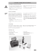
4.8 Switching off the system 4.10 Oxygen station C 248 Standby mode The C 200 does not have an integrated oxygen filling point for the decomposition vessel. You can use oxygen station C 248 for filling. The C 248 oxygen station must be set up at least 1.5 m far away from the calorimeter. For information on how to operate and connect the oxygen station, please see the accompanying operating instructions. In order to switch off the calorimeter system, the start screen must be displayed. Press OFF (F1).
5 Calorimetric measurements 5.1 Determining the calorific value Combustion is carried out in a calorimeter under specific conditions. The decomposition vessel is filled with a weighed fuel sample, the fuel sample is ignited and the temperature increase in the calorimeter system measured.
Note: in all the automatic calculations an extra 100 J have already been included for the electric ignition energy. This value cannot be set. Materials which are diffi cult to ignite or combust are combusted together with a burning aid. The burning aid is first weighed and then put into the crucible with the sample. The additional heat quantity can be determined from the weight of the burning aid and its known specific calorific value. You must correct the test result by this heat quantity.
5.4 Calibration The calorimeter system must be calibrated before accurate measurements are possible. This is done by combusting tablets made of certified benzoic acid (see Accessories) with a known calorific value. The heat quantity required to raise the temperature of the calorimeter system by one Kelvin is used to determine the heat capacity of the socalled "C-value" of the system. For this calculation the formula (1) (see section 5.
6.2 Preparing the decomposition vessel Prepare the decomposition vessel as follows: Cover Union nut Handle Cotton thread Attach a cotton thread to the centre of the ignition wire using a loop. Weigh out the substance directly into the crucible with an accuracy of 0.1 mg. Note the weight or enter directly into the calorimeter. (See section 6.3 "Preparing the measurement"). Insert the crucible into the crucible holder.
Attaching the ignition adaptor Detaching the ignition adaptor 6.3 Preparing the measurement The calorimeter is in ”waiting” mode. 1. 2. Selecting MEASUREMENT (F2) will take you to the "Prepare measurement" menu. Place the decomposition vessel into the inner vessel of calorimeter C 200. The decomposition vessel must be placed between the three locating bolts. Enter the noted weighted sample in the marked "Einwaage" (weighted sample) field with an accuracy of 0.0001 g using the keyboard.
QEXTERNAL2 Correction value for the heat energy from other burning aids e. g. combustible crucible). The default value is 0. TESTNO For each measurement the software automatically assigns a number in the form of yymmddnn, with jj representing the year, mm the month, dd the day and nn a consecutive number. You can also assign your own numbers to the measurements. Example: TestNo = 0509150 represents the first measurement on 15 September 2005 Press OK (F1) to apply your entries.
a) The measurement process is fully automatic for automatic measuring procedures (isoperibol, dynamic and time-controlled, see section 4.6). The result will appear once the measuring process is complete. After the measurement open the cover to automatically empty the inner vessel. Remove the decomposition vessel and the ignition adaptor. To release tension in the decomposition vessel use venting button under a fume hood or venting station C 5030 available in our accessories range.
The combustion residue in the crucible, e.g. soot or ashes, should also be wiped away with an absorbent non-fibrous cloth. 6.6 Errors in the measuring procedure Errors in the measuring procedure are shown in the alarm line of the display and remain there until they are appropriately acknowledged by the user. Message: Cover open! Cause: Sample not combusted. (Cotton thread had no contact to sample) User action: Open cover and remove decomposition vessel.
Message: Fill time exceeded Cause: Start temperature of inner vessel is not in range 22 ± 3 °C. User action: Open cover to cancel measurement, or press CONTINUE (F1) to continue the measurement anyway. Note: A measuring result obtained in this way does not correspond to the standard conditions. Cause: No water in tank. User action: Check the fill level in the tank and top up with water if necessary. Press CONTINUE (F1) to repeat the filling process and continue the measurement.
Meldung: Füllzeit überschritten 7 Service menu 7.1 Operation This menu allows you to directly control and test various actions and statuses of the calorimeter without performing a measurement. There are also menu items which can be used to start up and shut down the appliance. The service menu can only be run if the calorimeter displays the start screen. Perform the desired action using: Please note that you must stop every started action.
Pump Switch the pump on with this menu item. The outer vessel will be filled and rinsed (see also section 4.7). Requirement: Check that there is water in the tank. Reset This menu item allows you to restore the default settings. Reinit This menu item allows you to reinitialise the A / D converter. Empty outer vessel This menu item allows you to empty the outer vessel. Note: Shut-down, completely empty appliance. Requirement: The emptying hose must be locked in place in plug-in coupling (section 4.2).
• For cleaning the micro filter you must empty the outer vessel (see section 7.2). 8.4 Maintaining the water circulation In the case of discontinuous use with tap water (single measurements with long gaps) a stabiliser must be added to the water circulation to prevent the formation of algae. Add approx. 4 ml IKA®-Aqua-Pro C 5003.1 to the tank (see Accessories). Switch the pump on via the service menu (section “Pump“). Switch the pump off again after 30 - 60 s.
Comment: - Do not place electrical appliances into the cleaning agents for cleaning purposes. - Stainless steel parts can be cleaned using standard stainless steel cleaning agents, but do not use abrasives. - We recommend that you wear protective gloves for cleaning. - The operator is responsible for ensuring appropriate decontamination in the event that dangerous material is spilt onto or into the appliance.
10 Technical data Table power supply (external): Rated voltage Frequency Input power max. 100 - 240 V AC 50 / 60 Hz 150 W Calorimeter: Rated voltage Input power max. 24 V DC 5A 150 W Fuses (internal) Perm. on-time Protection class as per DIN EN 60 529 Protection class Overvoltage category Contamination level Perm. ambient temperature Perm.
Europe Middle East Africa IKA®- Werke GmbH & Co.KG Janke & Kunkel-Str. 10 D-79219 Staufen Tel. +49 7633 831-0 Fax +49 7633 831-98 sales@ika.de Asia Australia North America China IKA® Works, Inc. 2635 North Chase Pkwy SE Wilmington NC 28405-7419 USA Tel. 800 733-3037 Tel. +1 910 452-7059 Fax +1 910 452-7693 usa@ika.net sales@ikagz.com.cn IKA® Works Guangzhou 173 - 175 Friendship Road Guangzhou Economic and Technological Development District 510730 Guangzhou, China Tel.