iVIEWiVIEW-100 Series iVIEW-100/iVIEW-100-40 Handheld Controller User’s Manual Ver 2.0 / 2006/03 iVIEW-100 Series user’s Manual, 2006, v2.
iVIEWiVIEW-100 Series iVIEW-100/iVIEW-100-40 Handheld Controller User’s Manual Warranty All products manufactured by ICP DAS are warranted against defective materials for a period of one year from the date of delivery to the original purchaser. Warning ICP DAS assumes no liability for damages consequent to the use of this product. ICP DAS reserves the right to change this manual at any time without notice. The information furnished by ICP DAS is believed to be accurate and reliable.
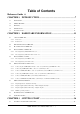
Table of Contents Reference Guide 6 CHAPTER 1. INTRODUCTION ...................................................................7 1.1 PACKAGE LIST.......................................................................................................................................................... 7 1.2 IVIEW-100 SERIES 1.3 FEATURES................................................................................................................................................................. 9 1.
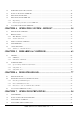
3.2 INSERT CD & INSTALL THE SOFTWARE ................................................................................................................... 38 3.3 DOWNLOAD PROGRAM TO IVIEW-100 ................................................................................................................... 40 3.4 EXECUTE PROGRAM FROM PC................................................................................................................................. 43 3.5 EXECUTE PROGRAM IN IVIEW-100 ...
7.5 USING COM2 FOR RS-485 APPLICATION ............................................................................................................... 99 7.6 COM PORT COMPARISON: IVIEW-100 & PC....................................................................................................... 100 7.7 HOW TO USE COM1/2 ......................................................................................................................................... 101 7.7.1 How to use COM.....................
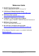
Reference Guide MiniOS7 Operating Description CD-ROM: \Napdos\MiniOS7\MiniOS7_2.0\”minios7.txt” I-7000 Series IO Module Selection Guide http://www.icpdas.com/products/Remote_IO/i-7000/i-7000_list.htm 7000 Series User’s manual http://www.icpdas.com/download/7000/manual.htm 7188XA/B/C & 7521/2/3 Series User’s Manual CD-ROM: \nopdos\7188XABC\7188XA/B/C\document\usermanual 8000 Series User’s manual CD-ROM: \nopdos\8000\”8000manual.pdf” 8K & 87K Series IO Module Selection Guide http://www.icpdas.
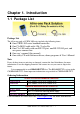
Chapter 1. Introduction 1.1 Package List Package List The all-in-one pack of iVIEW-100 series includes the following items: One iVIEW-100 series handheld controller One CA-M910 cable with 4 Di / 2 relay Do One CA-1509 cable with one RS-232 port, one RS-232/485 port, and one power connect line One user’s manual (this manual) One utility CD with Software drivers, demo programs & User’s Manual Note If any of these items are missing or damaged, contact the local distributors for more information.
1.2 iVIEW-100 Series The iVIEW-100 is a compact handheld controller with low cost / high performance text/graphic LCD display, specially designed for industrial environment that requires high reliability and PC-compatibility. The iVIEW-100, an all-in-one pack controller, can work independently with its own CPU, I/O Board, full keys Keypad, Text/Graphic LCD, inside buzzer and in-packed connecting cables to monitor and control the Data Inputs and Outputs.
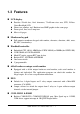
1.3 Features LCD display Provides 128x64 dots, 16x8 characters, 72x40 mm view area, STN, YellowGreen Backlight LCD Shows text, number, real, Boolean icon, BMP graphic in the same page Draws pixel, line, box, Lamp icon Max to 48 pages.
Allows C programming which can be downloaded from PC through COM1 via its in packed cable (CA-1509). Connects up to 64 numbers of remote I/O modules, and combines host PC, and power supply via its CA-1509 cable with one 5-wire RS-232 port, one RS232/485 port, and one power connect line. Real Time Clock Supports Real time clock with time & date. RTC leap year compensation from 1980 to 2079. Watchdog Built-in watchdog timer for harsh environment.
1.4 Specifications Power supply Power requirements 10 to 30 VDC power, Consumption: 3.
1.5 Contents of CD You can find all the iVIEW-100 series driver, manual & data files in the folder of CD\Napdos\iVIEW100, or you can reach to our FTP web site to find newly released information. Web site: http://www.icpdas.com/download/iVIEW-100_series.htm. CD : MiniOS7: driver, demo programs, utility software iVIEW-100 library files Source code of demo programs iVIEW-100 User’s Manual References are given in ReadMe.txt in the CD iVIEW-100 Series user’s Manual, 2006, v2.
Chapter 2. Hardware Information 2.1 View of iVIEW-100 2.1.1 Front view 2.1.2 Bottom view 11 6 1 Mini-DIN Connector 15 10 5 DB-15 Female Connector iVIEW-100 Series user’s Manual, 2006, v2.
2.2 Expanded picture of iVIEW-100 (1) (2) (3) iVIEW-100 (4) (5) iViEW-100= Upper CASE(1)+LCD(2)+I/O Board(3) + CPU Board(4) + Lower CASE(5) iVIEW-100 Series user’s Manual, 2006, v2.
2.3 Block Diagram of iVIEW-100 512K SRAM 512K Flash-ROM COM1 RS-232 COM2 RS-232/RS-485 RTC & NVSRAM 80188-40 Watchdog timer 16 bits timer EEPROM (2K) D/I,D/O Circuitry LCD Membrane Keypad +10V to +30V Power converter iVIEW-100 Series user’s Manual, 2006, v2.
2.4 Pin assignment of iVIEW-100 2.4.1 Pin assignment of Mini-DIN Connector 1 2 5 8 3 6 7 9 4 Mini-DIN Connector Pin assignment of Mini-DIN connector: Pin 1 2 3 4 5 Name DI1 DI2 DI3 DI4 DO PWR 6 Relay1+ DO1 Relay1DO2 Relay2+ DO3 Relay2DO4 7 8 9 Description Digital Input,3.5V~30V,channel1 Digital Input,3.5V~30V,channel2 Digital Input,3.5V~30V,channel3 Digital Input,3.
2.4.
2.5 Pin assignment of cables 2.5.1 Pin assignment of CA-M910 cable 1 2 5 8 3 6 7 9 4 Pin 1 2 3 4 5 Name DI1 DI2 DI3 DI4 DO PWR Color White Gray Yellow Brown Green 6 Relay1+ DO1 Relay1DO2 Relay2+ DO3 Relay2DO4 Black 7 8 9 Light Blue Red Blue 1 2 3 4 5 6 7 8 9 10 White Gray Yellow Brown Green Black Light Blue Red Blue Cable Shielding Shelding Description Digital Input,3.5V~30V,channel1 Digital Input,3.5V~30V,channel2 Digital Input,3.5V~30V,channel3 Digital Input,3.
2.5.2 Pin assignment of CA-1509 cable CA-1509 cable Connect to iVIEW-100 DB-9 Female Connector Com1:RS232 Connect to host-PC DB-15 Male Connector DB-9 Male Connector Com2:RS232/RS485 Red (24V+) Black (24V-) White (*Init) DB15-Male INIT * 24V+ 24C- 15 14 13 7 9 8 10 5 4 12 3 11 6 2 GND 1 RTS1 CTS1 9 8 7 6 RTS2 CTS2 DATA- 6 7 8 9 1 3 2 1 TXD1 3 5 4 DATA+ 2 4 5 GND RXD2 DB9-Male (COM2) iVIEW-100 Series user’s Manual, 2006, v2.
Pin assignment of COM1 connector (DB-9 Female connector of CA-1509): Pin 1 2 3 4 5 6 7 8 9 Name N/C TXD RXD N/C GND N/C CTS RTS N/C Description Transmit Data Receive Data Signal ground Clear To Send Request To Send Pin assignment of COM2 connector (DB-9 Male connector of CA1509): Pin 1 2 3 4 5 6 7 8 9 Name DATA+ RXD TXD N/C GND N/C RTS CTS DATA+ Description DATA+ pin Receive Data Transmit Data Signal ground Request To Send Clear To Send DATA- pin iVIEW-100 Series user’s Manual, 2006, v2.
2.6 Wiring diagrams for application 2.6.1 Connecting the COM1 (DB-9 Female connector of CA-1509) of iVIEW-100 to PC F5 F6 F7 Download Application Program from PC to iVIEW-100 F8 F1 F2 F3 F4 PWR RUN COM1 Shift ABC 1 2 GHI JKL 4 5 PQRS 7 TUV 8 DEF 6 B.S.
2.6.2 Connecting COM2 (DB-9 Male connector of CA-1509) to PC F5 F6 F7 F8 F1 F2 F3 F4 PWR RUN Shift ABC 1 2 GHI JKL 4 5 PQRS TUV 7 8 DEF 6 B.S. WXYZ 9 $%~ +-*/ 0 DB-9 Female 3 ESC MNO # POWER SUPPLY +10V~+30VDC Connector DB-15 Male Connector COM1/2 of HOST COMPUTER DB-15 DB-9 Female Connector COM1 CA-1509 CA-1518A DB-9 Male COM2 DB-9 Connector DB-9 Female DB-9 Connector Note: The CA-1509 cable has a female connector, a male DB-9 connector, and a power cable.
2.6.3 Connect COM2 (DB-9 Male connector of CA-1509) to the COM1 Port of I-8000 series F5 F6 F7 F8 F1 F2 F3 F4 PWR RUN Shift ABC 1 2 GHI JKL 4 5 PQRS TUV 7 8 DEF 3 ESC MNO 6 B.S.
2.6.4 Connecting COM1 (DB-9 Female connector of CA1509) to RS-232 Device F5 F6 F7 F8 F1 F2 F3 F4 PWR RUN Shift ABC DEF 1 2 3 GHI JKL MNO 4 5 6 PQRS TUV WXYZ 7 8 9 $%~ +-*/ 0 # ESC B.S. POWER SUPPLY +10V~+30VDC DB-15 Male Connector DB-9 Female Connector RS-232 DEVICE COM1 CA-1518A CA-1509 DB-9 Male Connector COM2 Note: The CA-1509 cable has a female DB-9 connector, a male DB-9 connector, and a power cable. The iVIEW-100 needs external power via power cable.
2.6.5 Connect COM2 (DB-9 Male of CA-1509) to RS-232 Device F5 F6 F7 F8 F1 F2 F3 F4 PWR RUN Shift ABC DEF 1 2 3 GHI JKL MNO 4 5 6 PQRS TUV WXYZ 7 8 9 $%~ +-*/ 0 # ESC B.S. POWER SUPPLY +10V~+30VDC DB-9 Female Connector RS-232 DEVICE DB-15 Male Connector CA-1509 CA-1518A COM1 COM2 DB-9 Male Connector DB-15 DB-9 Female Connector DB-9 Female Connector Note: The CA-1509 cable has a female DB-9 connector, a male DB-9 connector, and a power cable.
2.6.6 Connect COM2:RS-485 (DB-9 Male of CA-1509) to I-7000 & I-87K Remote I/O iVIEW-100 DB-9 Female, COM1 I-87K Remote I/O CA-1509 I-87K4 iVIEW-100 Pin 1 & 9 to Data+ & DataDB-9 Male COM2 Red(24V+) Black(24V-) White(*Init) DB-15 Male I-7000 Note: The CA-1509 cable has a female DB-9 connector, a male DB-9 connector, and a power cable. The iVIEW-100 needs external power via power cable. Refer to Sec.2.5 for more information about the pin assignment of cable.
2.7 DI/DO operating principle The iVIEW-100 has 4 digital inputs and 4 digital outputs. The 4 digital outputs can be configured as 2 relay outputs by pin assignment. The default setting is relay type.
2.7.1 Digital inputs byte definition & wiring DI byte definition is as follows: Bit 8 Bit 7 Bit 6 Bit 5 Bit 4 Bit 3 Bit 2 Bit 1 DI1 DI2 DI3 DI4 Relay 1 output state Relay 2 output state Test7: signal from outport bit 7 Test8: signal from outport bit 8 Wiring: Signal Ground: All digital inputs and outputs (except relay outputs) signal grounds are the same as the grounds of power used by the module.
2.7.2 Digital output definition & wiring: 2 Relay Outputs (default) DO byte definition: Bit 8 Bit 7 Bit 6 Bit 5 Bit 4 Bit 3 Bit 2 X X X Relay 1 Relay 2 Test 7 Test 8 Wiring N.O. iVIEW-100 6 relay 1 7 8 relay 2 block diagram iVIEW-100 Series user’s Manual, 2006, v2.
2.7.3 Digital output definition & wiring: 4 digital outputs DO byte definition: Bit 8 Bit 7 Bit 6 Bit 5 Bit 4 Bit 3 Bit 2 Bit 1 DO1 DO2 DO3 DO4 X X Test 7 Test 8 Wiring: Signal Ground: All digital inputs and outputs (except relay output) signal grounds are the same as the Power ground. Jumper setting: This kind of DO needs to re-config jumper setting.
iVIEW-100 5 VCC External power suply 6 DO1 7 DO2 8 DO3 9 DO4 iVIEW-100 Series user’s Manual, 2006, v2.
2.7.4 DI/DO operating method You can make commands in MiniOS7 Utility to test DI and DO. Please refer to Chapter 3 & 4 (especially section 3.4 & 4.3) to see how to use MiniOS7 Utility. The commands for testing DI & DO are listed below: Type Command Description DI i port Read data from the address of hardware port ( 0x104 ) DO o port value Output data value to the address of hardware port (0x105) Ex1: Make command i 0x104 to get DI value as below.
When user writes program for DI/DO, please use the following statements to get or set DI/DO value.
2.8 I/O expansion bus & ODM project The iVIEW-100 supports an I/O expansion bus. The I/O expansion bus can be used to implement various I/O functions such as D/I, D/O, A/D, D/A, Timer/Counter, UART, flash memory, battery backup SRAM, AsicKey & other I/O functions. Nearly all kinds of I/O functions can be implemented with this bus. Users can design their own I/O expansion board for their expansion bus. Each I/O expansion bus supports one expansion board only.
2.
Chapter 3. Getting Start Step 1: Connect to power supply & Host-PC. Step 2: Insert companion CD & install the software. Step 3: Download program to iVIEW-100. Step 4: Execute program from PC. Step 5: Execute program in iVIEW-100. Step 6: Auto-execute program in iVIEW-100. 3.1 Connect to power supply & Host-PC Step 1: Connect to power supply. User can connect to his own power supply or optional order from both our website and local agent. The DP-640 is a good choice for iVIEW100.
Step 5: Connect COM of PC to iVIEW-100. iVIEW -100 F5 F6 F7 ABC DEF PC DB-9 Female Connector F8 F2 F3 F4 PWR RUN F1 1 2 3 GHI JKL MNO PQRS TUV WXYZ 4 7 . +- * / 5 8 0 6 ESC B.S. 9 $ %~ # CA-1509 Connector Connect to COM1 or COM2 of host-PC DB-9 Male Connector DB-15 Male Connector Red(24V+) Black(24V-) White(*Init) iVIEW-100 Series user’s Manual, 2006, v2.
3.2 Insert CD & install the software Step: 1. Insert the companion CD. It will execute automatically. Step: 2. Click Toolkits (Softwares) / Manuals Step 3: Click iVIEW-100 Software & Libraries iVIEW-100 Series user’s Manual, 2006, v2.
Step 4: Copy all directories and files to the working directory of your disk driver. Or copy whole iVIEW100 directory to your disk. Step 5: Install MiniOS7 Utility. Double click the install file in the folder of minios7, follow the steps to install MiniOS7 Utility. Note: The download utility, MiniOS7 Utility, is used as a bridge between iVIEW100 & Host-PC. It can be used in the Microsoft Windows environment for the essential configuration and the programs download. The utility is similar to the 7188xw.
3.3 Download program to iVIEW-100 Step 1: Execute MiniOS7 Utility. If you have not done the steps of 3.1, follow the MiniOS7 Utility’s steps to connect iVIEW-100 to power supply and Host-PC. Step 2: Select the COM port that connected with Host-PC and the Baud rate. The iVIEW-100 use COM1 to download program from PC. The default Baud rate of iVIEW-100 is 115200. iVIEW-100 Series user’s Manual, 2006, v2.
Step 3: The left ListView show the files in the Host-PC. The right ListView show the files in the iVIEW-100. Select disk name from the Disk-Directory ComboBox. Select the folder and file from the left ListView below the Disk-Directory ComboBox. Example: C:\iview100\iviewapp\hello\ iVIEW-100 Series user’s Manual, 2006, v2.
Step 4: After choose a file from PC, click to download the file to iVIEW-100. When finish the access, the file will be shown in the right ListView. Example: C:\iview100\iviewapp\hello\hello.exe iVIEW-100 Series user’s Manual, 2006, v2.
3.4 Execute program from PC. Step 1: Double click the file name in the right ListView or select the file and then click the icon to run the program. hello User can also type the command in the MiniOS7 command line to access the program and see the result at the bottom of the window. Example: type hello, then press the Enter key to access the program. In this example, you can see the PC screen and the LCD of iVIEW-100 both show the word “Hello”. iVIEW-100 Series user’s Manual, 2006, v2.
Here is the content of Hello.c: #include "iVIEW.H" #include "mmi100.H" Include these two headers to use iVIEW-100’s user functions. int main() { InitLib(); Print("\n\rHello"); if(InitLCD()>0) Print("\n\rLCD wrong"); else { ClrScrn(); LcdPrintfAt(2,2,"Hello"); } return 0; } Initial iVIEW libaries. Print “Hello” on PC screen. Initial iVIEW LCD, if fail, print “LCD wrong” on PC. Clear LCD screen first. Print “Hello” on LCD (2,2). iVIEW-100’s LCD is a 16 characters(X) wide, 8 lines(Y) high screen.
If the program does not work or user wants to modify the program, after finish the modification, downloads the file again. iVIEW-100 will keep all the files until user deletes the files. When user wants to delete the files in iVIEW-100, please clicks the icon to delete all the files in iVIEW-100. Note: MiniOS7 provide the function to delete all existing files only. iVIEW-100 Series user’s Manual, 2006, v2.
3.5 Execute program in iVIEW-100 iVIEW-100 support user to run the program in the iVIEW-100 directly. iVIEW-100 has its own LCD display and full numeric membrane Keypad. After the program downloaded from PC, iVIEW-100 can access the program independently. This design makes the iVIEW-100 more suitable for harsh industrial environment. Before we execute program in iVIEW-100, we will introduce the keypad usage of iVIEW-100 to know how to use the keypad buttons to access the program. 3.5.
Usage of keypad for numbers and functions Keys are designed to input various characters like a mobile phone. Each key is divided into upper (blue) and lower (white) parts. The number value is in white. The Alphabet is in blue. For example: This key will be called Key “2” for convenience. White part F1 F2 F3 F4 1 2 3 4 5 6 7 8 9 . 0 # Blue part F5 F6 F7 F8 ,.: (not print) ABC DEF GHI JKL MNO PQRS TUV WXYZ +-*/ [Space] $%~ Use “Shift” Key to shift between White part and Blue part.
Here are some examples of number, Alphabet, or function key inputs: Example 1: Input “6”. This “character” is on the white part: Step 1: Make sure that LED light on the ‘Shift’ key is off. If on, press once to turn off. Step 2: Press “6” key once, LCD will show “6”. Example2: Input “S”. This letter is on the blue part of the “7” key of your console. Step 1: Press “Shift” key once to light-up the green LED on the “Shift” button. If the LED is already on, there is no need to press again.
Step 2: Press “7” key. The red LED on the “F1” button lights. Step 3: Press “7” key continously until the red LED of “F4” lights. (Push 3 times more.) Step 4: Press “F4” key or wait for 1 second to return “S” on the LCD. Step 5: Press “Shift” key. The green LED turns off. If you want to input other characters from the blue block, don’t press “Shift” key. Go to step 2. iVIEW-100 Series user’s Manual, 2006, v2.
Example 3: Input “F1”. Press “F1” key directly to return it’s value(0x81). Example 4: Input “F8”. This key is in the blue part of the “F4” key. Step 1: Press “Shift” key to light-up the green LED of “Shift” key. Step 2: Press “F4” to return 0x88. Step 3: Press “Shift” key to turns off the green LED. Note: The LED on F1~F4 won’t light in this situation. Example 5: input “space”(0x20). Press “Shift”. The green LED turns on. Press “0” to return 0x20. Press “Shift”. The green LED turn off.
3.5.2 Download program and execute in iVIEW-100 Step: 1. Download the file \iview100\iviewapp\LCD\LCD.exe from PC to iVIEW-100. Step: 2. Use keypad key in “LCD” to run LCD program. Press “Shift” key to light-up the green LED of “Shift” key. Press 3 times of “5” key to return the letter “L” onto LCD. Press 3 times of “2” key to return “C”, and 1 time of “3” key to return “D”. Press “Shift” key to turn off the green LED of “shift” key. Then press “Enter” key.
Here is the content of LCD.c: #include #include void main() { int quit=0; char c; InitLib(); InitLCD(); TextOutAt(5,3, "CHOOSE:"); TextOutAt(5,5, "1.LCD"); TextOutAt(5,6, "2.QUIT"); while(!quit) { c=Getch(); switch(c) { case '1': LCDSetToPage (2); ClrScrn(); TextOutAt(3,4, "* welcome *"); TextOutAt(1,8, "any key to back"); Getch(); break; case '2': quit=1; break; } LCDSetToPage (1); } ClrScrn(); CloseLCD(); } Include these two headers to use iVIEW-100’s user functions.
3.6 Auto-execute program in iVIEW-100 When developing software application, user can set the main program to auto-execute when the iVIEW-100 is powered up. The method is the same as in PC to set one autoexec.bat file. Step 1: Set the autoexec.bat file. Example: want to run LCD.exe menu when iVIEW-100 power up. The autoexec.bat file can just have one line include the file you want to call or more commands or files to access. But this file name has to be “autoexec.bat”. The content of autoexec.bat: LCD.
Chapter 4. Operating System - MiniOS7 The iVIEW-100 is a handheld controller with build-in MiniOS7 as its operating system. The MiniOS7 is an embedded Operating System designed for the iVIEW-100 series, I-7188/E/X series and I-8000 series. It is developed by ICP DAS Co. Ltd. Various companies have created several brands of DOS(Disk Operating System). In all cases, DOS (whether PC-DOS, MS-DOS, or ROM-DOS) is a set of commands or codes which tells the computer how to process information.
4.2 MiniOS7 Utility The MiniOS7 utility is used for the essential configuration and program download to the products embedded in the ICPDAS MiniOS7. The utility is similar to the 7188xw.exe (Windows console for Win32). However it can be used in the Microsoft Windows environment, rather than a window console environment. User can use MiniOS7 Utility to make command for MiniOS7. For larger screen mode, click the icon for switching between the large and small screen modes to see the result of the command.
4.2.1 Make MiniOS7 command To make MiniOS7 command, user just types command in the “MiniOS7 command Line” of MiniOS7 Utility. Example 1: type “date” to show the current date of RTC. Type “date mm/dd/yyyy” to set the date of RTC. Example 2: type “baud 115200” to set the baud rate to 115200. Example 3: type “dir” to show the information of all files downloaded in the FlashMemory. Example 4: type “hello” to run hello.exe program or type “run” to run the last file. iVIEW-100 Series user’s Manual, 2006, v2.
4.2.2 Toolbar and hot keys Toolbar There is one toolbar for MiniOS7 command line. It is at the left hand side of the command line. 1. : ASCII/HEX mode switch icon. 2. : Normal mode and line key-in mode switch icon. In Line mode, all characters-pressed will not send to COM until the ENTER is pressed. It is designed for testing the 7000 series. 3. : Run 7188xw.exe icon. 4. : Edit font icon. For changing the font, size and color of words in the screen. 5. : Edit color icon.
4.3 Typical commands of MiniOS7 Command USE NVRAM USE EEPROM USE Flash USE COM2 /option DATE mm/dd/yyyy] TIME [hh:mm:ss] MCB UPLOAD BIOS1 LOAD DIR [/crc] Description The service routine for read/write NVARM. The service routine of read/write EEPROM. The service routine of read/write Flash-ROM. The service routine of send/receive to/from COM2 (RS-485). Sets the date of RTC. Sets the time of RTC. Tests current memory block. The first step to update the MiniOs7. The last step to update the MiniOs7.
4.4 Upgrade MiniOS7 We will add more & more features to upgrade the MiniOS7. Please refer to our website to see if there any new version available. The MiniOS7 Utility provides an easy way to upgrade MiniOS7. Step 1: Please download the newest version of MiniOS7 file from website if necessary. And then decompress to the image file. The website is Http://ftp.icpdas.com.tw/pub/cd/8000cd/napdos/minios7/. The format of image file name is given as TTYYMMDD.
4.5 7188xw.exe Utility There is one more PC side utility program for MiniOS7--7188xw.exe. The 7188xw.exe is the Win32 Windows console programs for MiniOS7. 7188xw.exe supports RS-232 COM ports using USB and PCMCIA interfaces on Win32 systems. It link to the modules via RS-232 port of PC to access MiniOS7. 7188xw.exe basically is a terminal program. It sends out the data that user key-in to COM port, and show the data received from COM port on the screen of PC. The main function for 7188xw.
4.5.1 7188xw.exe commands & hot key Command line options of 7188xw.exe for MiniOS7: Option Description /c# Uses PC's COM# /b# Sets baud rate of PC’s COM port (default is 115200) /s# Sets screen’s display-rows (default is 25, max. is 50) Hot-key of 7188xw.exe: Command Description F1 Shows help messages of 7188xw.exe Alt_F1 Shows the Chinese (Big5) help messages of 7188xw.exe Ctrl_F1 Shows the Chinese (GB2312) help messages of 7188xw.
Alt_E For downloading files into memory. Only after the message “Press ALT_E to download file!” is shown on screen, users can press Alt_E. Alt_H Toggles Hex/ASCII display mode. Alt_L Toggles normal/line mode. In line-mode, all characterspressed will not send to COM until the ENTER is pressed. It is designed for testing the 7000 series. Alt_X Quits the 7188X.EXE. F2 Sets the file name for download (without download operation). F5 Runs the program specified by F2 and arguments set by F6.
Chapter 5. Libraries & compiler User must use C language to develop the application program for iVIEW-100-40 and iVIEW-100. We provide hundreds of functions in the libraries for user to call for C programming. When compile and link your programs, you can use TC 1.0~3.0, TC++ 1.0~3.0, BC 2.0, BC++ 3.1~5.02, MSC 8.00c or MSVC++ 1.52. You can download the freeware, TC 2.01 and the TC++ 1.01, from the website of Borland company: http://community.borland.com/museum. 5.
5.1.1 iVIEWL.lib There are hundreds of functions supported in iVIEWL.lib. You can see all their declarations in iVIEW.h. Here will list the most frequently used functions below. No Type 1 Standard IO Function Kbhit, Getch, Ungetch, Putch, Puts, Scanf, Print, ReadInitPin, LineInput….……... more …………….. 2 COM port InstallCom, InstallCom1, InstallCom2, InstallCom3…… RestallCom, RestallCom1, RestallCom2…… IsCom, IsCom1, IsCom2……, ReadCom, ReadCom1…… ClearCom, ClearCom1…, ToCom, ToCom1, ToCom2......
5.1.2 LCD library: mmi100.lib Please refer to mmi100.h to see the function declarations. All the LCD demo programs are in the folder of LCD. For more detail description and demo programs information please see the Appendix A: User function.
5.2 Compiler & linker When compile and link your programs, you can use TC 1.0~3.0, TC++ 1.0~3.0, BC 2.0, BC++ 3.1~5.02, MSC 8.00c or MSVC++ 1.52. User can download the freeware, TC 2.01 and the TC++ 1.01, from the website of Borland company: http://community.borland.com/museum. 5.2.1 Special settings and libraries information Please take care of the following items: 1. Generate a standard DOS executable program. 2. Select CPU=80188/80186 3. Select EMULATION if the floating-point computation is required.
5.2.2 Using Turbo C User can download Turbo C version 2.01 from the community website of Borland company: http://community.borland.com/article/0,1410,20841,00.html. Here are the working steps to use TC 2.01. Step 1: Copy the lib files, iviewL.lib & mmi100.lib, of iVIEW-100 to the “lib” folder of TC. Ex: Copy iviewL.lib & mmi100.lib to c:\tc\lib. Step 2: Copy the .h files, iview.h & mmi100.h, of iVIEW-100 to the “include” folder of TC. Ex: Copy iview.h & mmi100.h to c:\tc\include.
Step 5: Edit a new file as its project file. Ex: The “HELLO1.PRJ” for the program “HELLO1.C”. The content of HELLO1.PRJ is as following: Hello1.c C:\tc\lib\iviewl.lib C:\tc\lib\mmi100.lib Step 6: Set the project name as following: Step 7: The setting of compiler model and options are given as following: iVIEW-100 Series user’s Manual, 2006, v2.
Step 8: Disable source debugging in the DEBUG field. Step 9: Compile and Make to generate “HELLO1.EXE”. Or you can press F9 key to do the same job. iVIEW-100 Series user’s Manual, 2006, v2.
5.2.3 Using Turbo C++ User can download Turbo C++ version 1.01 from the community website of Borland company: http://community.borland.com/article/0,1410,21751,00.html. Here are the working steps to use TC++ 1.01. Step 1: Copy the lib files, iviewL.lib & mmi100.lib, of iVIEW-100 to the “lib” folder of TC++ (Ex:TCPP). Ex: Copy iviewL.lib & mmi100.lib to c:\tcpp\lib. Step 2: Copy the iview.h & mmi100.h files of iVIEW-100 from CD to the “include” folder of TC++. Ex: Copy iview.h & mmi100.
Step 4: Open a new project file. Ex: A new “HELLO2.PRJ” for the program “HELLO2.C”. Click the function menu of “Project\Open project…”, then type the project name “HELLO2.PRJ” in the same directory of “HELLO2.c”, then click “OK”. iVIEW-100 Series user’s Manual, 2006, v2.
Step 5: Add library files into the project. Click the project area, then select “Project\Add Item…”, click “HELLO2.C” and then click “Add” to add “HELLO2.c” into the project. Use the same method to add “TCPP\LIB\iVIEWL.LIB” and “TCPP\LIB\MMI100.LIB” into the “HELLO2.PRJ”. iVIEW-100 Series user’s Manual, 2006, v2.
Step 6: Set the “Options\Compiler\Code generation…” as following: Click “More” to set “Advanced Code Generation” as following: iVIEW-100 Series user’s Manual, 2006, v2.
Step 7: Set the “Options\Debugger” as following: Step 8: Select “Options\Save…” to save options. iVIEW-100 Series user’s Manual, 2006, v2.
Step 9: Pressing “F9” will compile and link program to generate “HELLO2.EXE”. iVIEW-100 Series user’s Manual, 2006, v2.
Chapter 6. Demo programs 6.1 Demo programs list There are many demo programs given in iview100\iviewapp\*.* as follows: No Execution file Folder Function Short explanation 1 Hello.exe Hello For beginning 2 Hello1.exe TC For beginning 3 Hello2.exe TCPP For beginning 4 Stdio.exe Stdio Standard IO 5 Keypres.exe Keypad Keypad 6 Cal.exe Keypad 7 Stdio2.
No Execution file Folder Function Short explanation 22 Comt.exe COM COM Show how to use COM functions, ‘Q’ to quit. 23 Comt1.exe COM COM Shows how to use COM1 functions, ‘q’ to quit. 24 Icom2.exe COM COM Shows how to use COM fuctions 25 Comts.exe COM COM 26 Lcdin.exe Lcd LCD: initial Shows iVIEW-100 how to communicate with Windows Hyper Terminal of PC. Both can type and receive message. Shows how to initial and test LCD 27 Vlnts.exe Lcd LCD: draw Draws vertical line on LCD. 28 Hln.
No Execution file Folder Function Short explanation 48 Sound1.exe Sound Sound Plays sound. 49 7000.exe 7000 50 Com2o.exe 7000 Connect: 7000 Sends commands to I-7065D, controls the Do lights. Connect: 7000 Sends cmd to I-7065D, and shows cmd on PC & LCD (Use ToCom, ReadCom) 51 Ts7065.exe 7065 52 Ts7065d3.exe 7065 Connect: 7065 Uses iVIEW keypad & the menu on LCD to control and moniter the 4DI, 5DO of I-7065D.
6.2 Detail explanation for some demo programs 6.2.1 Demo Keypad & LCD: Keypres.c Purpose: This demo program shows how to control iVIEW-100 keypad & LCD display, and show keypad’s ASCII code for future programming control. Lib included: iVIEW.h & mmi100.h Variables: Name quit chr x Type int int int y int j data[10] int char Default Description 0 When quit=1, quit this program. For the input key value(ASCII code) 1 Trace the X character position of LCD. X must between 1 and 16.
InitLCD(); /* initial LCD */ LcdSetCursorOn(); /* Display cursor */ while(!quit) { chr=Getch(); if(y==9) { /*LCD line(y)<=8*/ ClrScrn(); y=1; } if(chr=='q') quit=1; /*if input ‘q’, quit the program*/ else if(chr<0x80) Print("%c",chr); /*print input letter*/ Print("[%d]",chr); /*print ASCII code*/ if (j==10) j=0; /*count input to make sure 0<=j<10*/ data[j]=(char)chr; Print(" %c @LCD(%d,%d) [%d]\r\n",data[j],x,y,j+1); //print (x,y) LCD location j=j+1; if (chr==8) { x=x-1; TextOutAt(x, y, (char *)&chr); x=x-1
6.2.2 Demo all LCD functions: tsmi.c Purpose: This demo program shows how to control iVIEW-100 LCD display. It uses almost all the functions in mmi100.lib. You can learn how to use the ‘page’ function to make different menu, how to show lamp for light on & off, how to show BMP black/white picture on LCD… Download files: For download files method, please refer to Chapter 3.3. tsmi.exe ee.bmp i.bmp kb.bmp c.bmp d.bmp Lib included: iVIEW.h & mmi100.
{ int quit=0; int x, y, page; char c; static uchar LampON[8] ={0X00, 0X5A, 0X24, 0X42, 0X42, 0X24, 0X5A, 0X00}; InitLib(); InitLCD(); Box(10, 10, 118, 54, 1); DrawText(13, 3, LampON); LCDBright (5); SetCursorLine(8); SetCursorAt(13, 3); GetCursorAt(&x, &y); UnderLine(x,y, 1,1); TextOutAt(3,3, "CHOOSEone:"); TextOutAt(3,4, "a.TEXT b.BMP"); TextOutAt(3,5, "c.FLASH"); TextOutAt(3,6, "q.
TextOutAt(4,5,"TEST MMI"); lamp (13,3,1); TextOutAt(1,7, "any key to back"); page=GetLCDPage(); TextOutAt(1,8, "page=a="); IntOutAt(8, 8, 1, page ); Getch(); break; case 'b': case 'B': LCDSetToPage (3); ClrScrn(); LCDBright (7); page=GetLCDPage(); SetCursorLine(0); TextOutAt(3,1, "8 LINES LCD"); TextOutAt(2,2, "48 PAGES"); TextOutAt(3,3, "8 BRIGHT SETS"); TextOutAt(1,6, "SHOW:"); TextOutAt(1,7, "1.icon: "); DrawText( 9,7, LampON); TextOutAt(1,8, "2.graphic:"); BmpShowAt(13, 26, "ee.
while(!Kbhit()) { LCDBright (1); BmpShowAt(20, 10, "c.bmp" ,1); LCDBright (7); BmpShowAt(20, 10, "d.bmp" ,1); } break; case 'q': case 'Q': quit=1; break; } LCDSetToPage (1); } ClrScrn(); CloseLCD(); } Show 2 BMP picture alternately on LCD. Using the similar pictures & contrasted bright seting to mke an animation effect. Press any key to back to page 1. //press ‘q’ or ‘Q’ to quit this program //back to LCD page 1 //Clear LCD screen //close LCD iVIEW-100 Series user’s Manual, 2006, v2.
6.2.3 Demo how to connect to I-7000 module: ts7065d3.c Purpose: This demo program shows how to connect iVIEW-100 and I-7000 I/O module. Using iVIEW’s keypad moniter the Di & control the Do of I-7065D(with 4 Di, 5 Do display light). Lib included: iVIEW.h & mmi100.h Variables: Name port x y i j n c check Type int int int int int int int int color int coloro int quit int Dotemp int DiCT[4] int DoCT[5] int doON[5] int Default 2 Description Set port 2 to connect to I-7000 module.
diR[6] char doT[7] char tt char To store the Di Read respond value. For ‘&’ with DiCT value to decide which Di light is ON or OFF. To store the command send to control the Do lights. A temporary storage for Di respond value when use ReadCom command. Program : #include #include
InstallCom(port,115200L,8,0,1); //install COM port 2, baud rate:115200 ClearCom(port); //clear Com before read or send to Com SendCmdTo7000(port, "@0100",0); //send Do all off command ClearCom(port); SendCmdTo7000(port, "@01",0); //send Di read command //show Di while(!quit) { while (IsCom(port) ) //while COM has any data, begin to decode { tt=ReadCom(port); if(tt == '>' || diR[0] =='>' ) //the first data of available respond is ‘>’ { If data is available respond, store them if(tt=='>') j=0; to diR[j] diR[j
} }//end (IsCom()) //control Do If there any keyboard input, begin the if(Kbhit()) Do control process.
Print("do= %c \r\n", doT[i]); } ClearCom(port); SendCmdTo7000(port, "@01",0); }//end if up & down Key }// if quit!=1 }//end if Kbhit() }//while loop ClrScrn(); CloseLCD(); } iVIEW-100 Series user’s Manual, 2006, v2.
6.3 Local language Bitmap solution The iVIEW-100 series can show any local language via the BMP graphic solution. Any language, such as Japanese, French, Russian, Italian, Chinese, Indian…, can be shown in bitmap graphic files, can be shown on iVIEW-100 series’ LCD. How to show local language on the LCD of iVIEW-100? Please follow the steps: Step 1: Prepare the local language text into bipmat graphic files. The graphics must be black/white, bitmap format (BMP), and not larger than 128x64 pixel.
Step 2: Write a program to call the BMP files. The user function to call BMP file is: BmpShowAt(int X, int Y, “BMP_File_Name.bmp”, color); Please refer to ‘Appendix A.2.2 Type2: Draw & BMP picture (pixel)’ for detail usage. Compile and link your program to generate the execution file (.exe). Ex: Loclang.c (The loclang.exe is in the folder ‘Loclang’ of CD) #include #include void main() { InitLib(); InitLCD(); TextOutAt(2,1, "LOCAL LANGUAGE"); UnderLine(2,1,14,1); BmpShowAt(8,10,"bmpch1.
Step 3: Download the execution file and all BMP files into iVIEW-100. The files you need to download include the execution program file and all the BMP files that will be called by the execution file. You can download files to iVIEW-100 by using MiniOS7 Utility or 7188xw.exe Utility. Please refer to Chapter 3.5.2 (for MiniOS7 Utility) or Chapter 4.5 (for 7188xw.exe Utility) for ‘how to download program and execute program in iVIEW-100’. Ex: Please download all the files in the folder ‘loclang’ of CD.
Chapter 7. Operation Principles 7.1 System Mapping Device SRAM Flash ROM COM1 BASE COM2 BASE Address mapping From 0000:0000 to 7000:FFFF From 8000:0000 to F000: FFFF 0x200 0x100 Interrupt No. 0 1 2 3 4 5 6 7 8 9 0A 0B INT0 INT1 0E-10 12 13 Interrupt mapping Divided by zero Trace NMI Break point Detected overflow exception Array bounds exception Unused opcode exception ESC opcode exception Timer 0 Reserved DMA-0 DMA-1 COM1 COM2 Reserved Timer 1 Timer 2 iVIEW-100 Series user’s Manual, 2006, v2.
Two independent COM port: Port COM1 COM2 Description • For general purpose 3-wire RS-232 application • UART-0 of 80188 • Direct control 7000 series modules • For general purpose 3-wire RS-232 application • For general purpose 2-wire RS-485 application • UART-1 of 80188 WARNING 1: The COM2 is not isolated to CPU. If there is large noise in the RS-485 network, the iVIEW-100 may be damaged. It is recommended to add an I-7510 repeater between the COM2 & external RS-485 network for harsh environments.
7.2 Download/debug program with COM1 The COM1 of iVIEW-100 has three major functions. The first function is to download program from PC. The second function is to link PC for program debug. The last function is as a general-purpose COM port. When the iVIEW-100 is powered-up, it initializes COM1 to the following configuration: Start-bit=1, data-bit=8, stop-bit=1, no parity Baud rate = 115200 Then the iVIEW-100 will check the state of INIT*-pin.
7.3 Using COM1 as a COM Port The user can use COM1 as a general purpose RS-232 port as follows: Download user’s program & autoexec.bat to iVIEW-100 first. Power off iVIEW-100 & remove the download cable from PC. Disconnect the INIT*-pin from GND-pin of iVIEW-100 if they are connected Power on iVIEW-100 (no standard input, no standard output, no debug information) Install the download cable between new RS-232 device & COM1 of iVIEW100 Initializes the COM1 to new configuration.
7.4 Using COM2 for RS-232 Application The COM2 is a 5-wire RS-232 port. It includes the following 5 pins: GND: signal ground TXD2: transmit data to external RS-232 device RXD2: receive data from external RS-232 device RTS2: request to send CTS2: clear to send Refer to Chapter 2.6.2 for wire connection iVIEW-100 Series user’s Manual, 2006, v2.
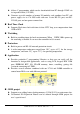
7.5 Using COM2 for RS-485 Application The COM2 is a 2-wire RS-485 port. It includes the following 2 pins: Pin1(D2+) : connect to DATA+ of RS-485 network Pin9(D2- ) : connect to DATA- of RS-485 network The COM2 is a half-duplex 2-wire RS-485 network. It cannot be used in the fullduplex 4-wire RS-485 application. It is designed to directly drive I-7000 series modules. The working steps for I-7000 related applications are given as follows: 1. 2. 3. 4.
7.6 COM port Comparison: iVIEW-100 & PC The COM ports of iVIEW-100 are as following: COM port COM1 COM2 Hardware UART-0 of 80188 UART-1 of 80188 The programming of 16C550 is very different to 80188’s UART. The interrupt handling of 80188 is also very different to PC’s 8259. Therefore if user downloads the PC’s RS-232 application program into iVIEW-100, it will not work. The software driver of iVIEW-100 is an interrupt driven library, which provide 1K QUEUE buffer for every COM port.
7.7 How To Use COM1/2 The iVIEW-100 has 2 communication ports. COM1 is an RS-232 port. COM2 can be used as an RS-232 or RS-485 port. 7.7.1 How to use COM Before using the COM port, user must call “InstallCom” (or InstallCom1/2) to install the driver for the COM port. Before exiting the program, user must call “RestoreCom” (or RestoreCom1/2) to un-install the driver. After calling “InstallCom”, the user could read COM data, send data to COM, print COM data, and so on.
Use the variable port to change from using COM1 to using COM2, just change port=1; to port=2.(see Note below) If the program is fixed to use COM1, the code can be altered as follows.
7.7.2 How to print COM The library of iVIEW-100 also supports functions like printf of standard C library to produce a formatted output. printCom is for all comports, printCom1/2 are for individual port. Before using printCom you must call up InstallCom. Here’s the code.
7.7.3 How to send command to I-7000 The RS-485 (COM2) is designed to directly drive I-7000 series modules. The commands for I-7000 series modules are very different from those of iVIEW-100, but we can send the command from iVIEW100 to I-7000 by using “ToCom”. The example code for sending command to COM2 (RS-485) is listed below.
7.8 How to use Flash memory The iVIEW-100 series module has 512K Flash of memory. It contains the MiniOS7 and the ROM-DISK. MiniOS7 occupies segment 0xF000 (the last segment). The ROM-DISK occupies the first segment, such as 0x8000 for 512K memories. So iVIEW-100 will occupy at least two segments. The user can use non-used segments to store data. With 512K memory, there is a maximum 384K of memory left to store data. Flash memory can be written from 1 to 0 only and can’t be written from 0 to 1.
7.9 RTC & NVSRAM The RTC & NVSRAM are located on the same chip. There is a Li-battery to backup the RTC & NVSRAM for 10 years. The features of RTC are given as follows: Year 2000 Compliance BIOS support RTC time & date MiniOS7 support RTC time & date Seconds, minutes, hours, date of the month Month, day of week, year, (Leap year valid up to 2079) NVSRAM: 31 bytes The NVSRAM can be read/write any number of times.
7.10 Use EEPROM The EEPROM is designed to store infrequently changed data. For example: Module ID configuration settings COM port configuration settings Small data base The erase/write cycle of EEPROM is limited(1,000,000 erase/write cycles), user should not change the EEPROM frequently for testing. The EEPROM can erase/write onto a single byte, so it is very useful in real world applications. The iVIEW-100 has 2K bytes of EEPROM. The EEPROM contains 8 blocks and each block has 256 bytes.
7.11 Watchdog timer The watchdog timer of iVIEW-100 is fixed at 0.8 second. User can call watchdog function in user program. The user program tell the MiniOS7 to refresh the watchdog timer, and then the user program can stop & return to the prompt of MiniOS7. If the iVIEW-100 does not refresh watchdog timer in 0.8 second, the watchdog will RESET the iVIEW-100. The MiniOS7 of iVIEW-100 will automatically refresh the watchdog after first power on.
The function IsResetByWatchDogTimer is used to check whether the iVIEW100 has been reset by WatchDog Timer. This function must be inserted on the beginning of program. The code can be as follows.
Appendix A. User function A.1.
K S Kbhit, 114 L lamp, 151 LCDBright, 154 LcdPrintfAt, 150 LCDSetToPage, 155 Line, 148 LineInput, 116 P Pixel, 147 Print, 115 printCom, 120 printCom1, 120 ProtectEEP, 122 Putch, 115 Puts, 115 Scanf, 115 SendCmdTo7000, 142 SetCursorAt, 153 SetCursorLine, 152 SetDate, 126 SetTime, 125 StopWatchContinue, 133 StopWatchPause, 133 StopWatchReadValue, 134 StopWatchReset, 133 StopWatchStart, 132 StopWatchStop, 133 T R ReadCom, 119 ReadCom1, 119 ReadEEP, 123 ReadInitPin, 116 ReadNVRAM, 124 RealOutAt, 151 Rece
A.2. iVIEWL.lib “iVIEWL.lib” is the main user function library for iVIEW-100. It contains most of the iVIEW-100 functions. The other user function, “mmi100.lib”, specially focuses on LCD usage. Please include the header files “iVIEW.h” & “mmi100.h”, and add “iVIEWL.lib” & “mmi100.lib” into the project to implement the user function. No Type 1 Standard IO Function Kbhit, Getch, Ungetch, Putch, Puts, Scanf, Print, ReadInitPin, LineInput….……... more ……………..
A.2.1 Type 1: Standard IO Function Kbhit Getch Ungetch Putch Puts Scanf Print ReadInitPin LineInput ……more…… Description Checks if any key board hit data is currently available in the input buffer of COM1. Wait until get one character from key board hit. Put one character back to COM1's input buffer. Send one character to COM1. Send a string to COM1. Get a formatted data like C's scanf. ( cannot used on MSC / VC++, just TC/BC only) Print a formatted data like C’s printf. Read the status of INIT* pin.
Kbhit() Func.: Checks if any key board hit data is currently available in the input buffer. Syntax: int Kbhit(void); Header: #include ”mmi100.h” Description: Checks if any data is currently available in the input buffer. Return 0 : for no data input. Return Others : Has data in input buffer, and the return value is the next data in buffer, if the next data is '\0' it will return -1(0xFFFF). Example: #include (stdio.c) #include
Putch() Func.: Syntax: Send one character on screen. void Putch(int data); Header: #include ”mmi100.h” Description: data: 0 to 255. If data > 255, only the low byte will be send out. Example: Please refer to “Kbhit()” for example. Puts() Func.: Syntax: Send a string on screen. void Puts(char *str); Header: #include ”mmi100.h” Description: Puts will call Putch to send the string. str: The pointer to the string to be send. Example: Please refer to “Kbhit()” for example. Scanf() Func.
LineInput() Func.: Syntax: Header: Description: Input one line from StdInput. int LineInput(char *buf, int maxlen); #include ”mmi100.h” buf: The buffer to store the input data. maxlen: (size of the buffer)-1. Return Value: The input character number. Example: ReadInitPin() Func.: Syntax: Header: Description: Example: (stdio2.c) Read the status of INIT* pin. int ReadInitPin(void); #include ”mmi100.h” Return: 0= Init* pin is floatting or connect to VCC. Return: 1= Init* pin is connect to GND.
A.2.
InstallCom () Func.: Install COM driver Syntax: int InstallCom(int port, unsigned long baud, int data, int parity, int stop); Header: #include ”iVIEW.h” Description: Install driver to COM, COM number is not fixed port: assigning for COM port number, different “port” different COM baud: baud rate, iVIEW-100 default baud rate=115200 Example: #include (comt.c) #include
RestoreCom() Func.: Syntax: Un-install COM driver, COM number is not fixed int RestoreCom(int port); Header: #include ”iVIEW.h” Description: Un-install COM driver, COM number is not fixed port: assigning for COM port number Example: Please refer to “InstallCom()” for example. RestoreCom1() Func.: Syntax: Un-install COM1 driver, fix on COM1 int RestoreCom1(void); Header: #include ”iVIEW.h” Description: Un-install COM1 driver, fix on COM1 Example: Please refer to “InstallCom1()” for example.
ClearCom() Func.: Syntax: Clear all the data in COM, COM number is not fixed int ClearCom(int port); Header: #include ”iVIEW.h” Description: Clear all the data in COM, COM number is not fixed Example: Please refer to “InstallCom()” for example. ClearCom1() Func.: Syntax: Header: Description: Example: Clear all the data in COM1, fix on COM1 int ClearCom1(void); #include ”iVIEW.h” Clear all the data in COM1, fix on COM1 Please refer to “InstallCom1()” for example. ToCom() Func.
A.2.3 Type 3: EEPROM Function EnableEEP WriteEEP ProtectEEP ReadEEP InitEEPROM ……more…… Description Enable EEPROM to write-enable mode Write data to EEPROM Set EEPROM to write-protect mode Read data from EEPROM Before calling external EEPROM function, have to call InitEEPROM() first. There are more user function for EEPROM, please refer to Appendix C iVIEW.h and CD\Napdos\7188 \miniOS7\manual\index.html for more detail information. Note: There are two types of EEPROM for iVIEW-100, 24LC16 & 24LC1024.
EnableEEP() Func.: Syntax: Enable EEPROM to write-enable mode void EnableEEP(void); Header: #include ”iVIEW.h” Description: Enable EEPROM to write-enable mode EEPROM is default in write-protect mode, must call EnableEEP() before writing data to EEPROM. Example: #include (eep.c) #include void main() { Int data=55, data2; InitLib(); EnableEEP(); WriteEEP(1,10,data); ProtectEEP(); data2=ReadEEP(1,10); Print("data=%d, Data2=%d",data,data2); } WriteEEP() Func.
ReadEEP() Func.: Syntax: Read data from EEPROM int ReadEEP(int block, int addr); Header: #include ”iVIEW.h” Description: Read one byte data from EEPROM. block: 0 to 7 (total 8 blocks). addr: 0 to 255 (every block has 256 bytes). Return Value: On success return the value on EEPROM(0 to 255). On fail return Error code. BlockError(-10) or AddrError(-9) or (-101,-102 for read error).. Example: Please refer to “EnableEEP()” for example. InitEEPROM() Func.
A.2.4 Type 4: NVRAM & RTC Function ReadNVRAM WriteNVRAM GetTime SetTime GetDate SetDate GetWeekDay ……more…… Description Read data from NVRAM. Write data to NVRAM. Get the system time from the RTC. Set the system time to the RTC Get the system date from the RTC Set the system date to the RTC Get the weekday to the RTC. There are more user function for NVRAM & RTC, please refer to Appendix C iVIEW.h and CD\Napdos\7188 \miniOS7\manual\index.html for more detail information. ReadNVRAM() Func.
WriteNVRAM() Func.: Syntax: Write data to NVRAM. int WriteNVRAM(int addr, int data); Header: #include ”iVIEW.h” Description: Write one byte data to NVRAM. addr: 0-30. data: One byte data (0-255). If data>255, only the low byte will be write to NVRAM. Return Value: On success return NoError. On fail return AddrError(-9). Example: Please refer to “ReadNVRAM()” for detail information. GetTime() Func.: Syntax: Get the system time from the RTC.
Func.: Syntax: Header: Description: Example: Read the system date from the RTC void GetDate(int *year,int *month,int *day); #include ”iVIEW.h” year: 2000-2080 month: 1-12 day: 1-31 Please refer to “GetTime()” for detail information. SetDate() Func.: Syntax: Header: Description: Example: Set the system date to the RTC int SetDate(int year,int month,int day); #include ”iVIEW.h” year: 2000-2080 month: 1-12 day: 1-31 Return Value: On success return NoError. On fail return DateError(-18).
A.2.5 Type 5: Flash Memory Function FlashReadId FlashErase FlashWrite FlashRead Description Get the information about FLASH. ERASE one sector of flash. Write one byte data to FLASH. Read one byte data from FLASH. There are more user function for Flash Memory, ……more…… please refer to Appendix C iVIEW.h and CD\ Napdos\7188\miniOS7 \manual\index.html for more information. The size of the Flash Memory used on iVIEW-100 series is 512K bytes.
FlashWrite() Func.: Syntax: Write one byte data to FLASH. int FlashWrite(unsigned int seg, unsigned int offset, char data); Header: #include ”iVIEW.h” Description: seg: 0x8000, 0x9000, 0xA000, 0xB000, 0xC000, 0xD000 or 0xE000. offset: 0 to 65535(0xffff). data: 0 to 255(8-bit data). Return NoError(0) on success. Return TimeOut(-5) or SegmentError(-12) on fail. Note: When write data to Flash Memory, data bit only can be changed from 1 to 0.
A.2.6 Type 6: Timer & Watchdog Timer Function TimerOpen TimerClose TimerResetValue TimerReadValue DelayMs Description Open timer function usage. Stop timer function. Reset timer to 0. Read main time ticks. Delay some time interval. The time unit is ms, use system timeticks. Delay Delay some time interval. The time unit is ms, use CPU Timer 1. Delay_1 Delay some time interval.The time unit is 0.1 ms, use CPU Timer 1. Delay_2 Delay some time interval.The time unit is 0.01 ms, use CPU Timer 1.
TimerOpen() Func.: Syntax: Open timer function usage. int TimerOpen(void); Header: #include ”iVIEW.h” Description: Before use any timer function must call TimerOpen On success return NoError. If Timer is already opend,return 1. Example: #include (tmr.c) #include
TimerClose() Func.: Syntax: Stop timer function. int TimerClose(void); Header: #include ”iVIEW.h” Description: If the program has call OpenTimer, it must call TimerClose before exiting. Always return NoError. Example: Please refer to “TimerOpen()” for detail information. TimerResetValue() Func.: Syntax: reset timer to 0. void TimerResetValue(void); Header: #include ”iVIEW.h” Description: Reset the main time ticks to 0. Example: Please refer to “TimerOpen()” for detail information.
Delay_1() Func.: Syntax: Delay some time interval; the time unit is 0.1 ms, use CPU Timer 1. void Delay_1(unsigned ms); Header: #include ”iVIEW.h” Description: Delay some time interval. Delay unit is .01 ms, use CPU Timer 1. ms: the time want to delay. Example: Please refer to “TimerOpen()” for detail information. Delay_2() Func.: Syntax: Delay some time interval; the time unit is 0.01 ms, use CPU Timer 1. void Delay_2(unsigned ms); Header: #include ”iVIEW.
StopWatchReset() Func.: Syntax: Reset the StopWatch value to 0. int StopWatchReset(int channel); Header: #include ”iVIEW.h” Description: channel:0-7, total 8 channels. If channel is out of range return ChannelError(-15). On success return NoError. Example: Please refer to “StopWatchStart()” for detail information. StopWatchStop() Func.: Syntax: Disable the StopWatch channel. int StopWatchStop(int channel); Header: #include ”iVIEW.
StopWatchReadValue() Func.: Syntax: Read current StopWatch value. int StopWatchReadValue(int channel,unsigned long *value); Header: #include ”iVIEW.h” Description: The value stand for the time from call StopWatchStart/StopWatchReset to now.channel:0-7, total 8 channels If channel is out of range return ChannelError(-15). If success return NoError. Example: Please refer to “StopWatchStart ()” for detail information. CountDownTimerStart() Func.: Syntax: Header: Description: Example: (codn.
InstallUserTimer() Func.: Syntax: Install user's timer function. User's timer function will be called every 1 ms. void InstallUserTimer(void (*fun)(void)); Header: #include ”iVIEW.h” Description: fun: The user's function pointer. The function cannot use input agument, and can not return value. Example: #include (ustm.c for 5 #include
InstallUserTimer1C() Func.: Install user's timer function on interrupt 0x1c. System timer will call int 0x1c every 55 ms. Syntax: void InstallUserTimer1C(void (*fun)(void)); Header: #include ”iVIEW.h” Description: fun: The user's function pointer. The function cannot use input agument, and can not return value. Example: Please refer to “InstallUserTimer()” for silimar information. EnableWDT() Func.: Syntax: Enable the Watchdog timer. void EnableWDT(void); Header: #include ”iVIEW.
DisableWDT() Func.: Syntax: Disable the Watchdog timer. void DisableWDT(void); Header: #include ”iVIEW.h” Description: See the Description of EnableSDT(). Example: Please refer to “EnableWDT ()” for deatil information. RefreshWDT() Func.: Syntax: Header: Description: Example: Refresh the Watchdog timer. void RefreshWDT(void); #include ”iVIEW.h” See the Description of EnableSDT(). Please refer to “EnableWDT ()” for deatil information. IsResetByWatchDogTime() Func.
A.2.7 Type 7: file Function GetFileNo GetFileName GetFilePositionByNo GetFileInfoByNo GetFileInfoByName …………more………… Description Get total number of files stored in Flash Memory. Use file index to get file name. Use file number to get file position. Use file number to get file information. Use file name to get file information. There are more user function for file, please refer to Appendix C iVIEW.h and CD\Napdos\7188\miniOS7\manual\ind ex.html for more information.
GetFilePositionByNo() Func.: Syntax: Use file number to get file position. char far *GetFilePositionByNo(int no); Header: #include ”iVIEW.h” Description: User can use the address to get file data. no: The file index (The first file is index 0). On success return the start address of the file.On fail return NULL. Note: If file size > 64K-16, must use a huge pointer(char huge *) to get file data for offset >64K-16 Example: static FILE_DATA far *fdata; /*file_data structure, please see the file.c*/ (file.
GetFileInfoByNo() Func.: Syntax: Use file number index to get file information. FILE_DATA far *GetFileInfoByNo(int no); Header: #include ”iVIEW.h” Description: no: The file index (The first file is index 0). On success return the start address of the file information.On fail return NULL. Example: Please refer to “GetFilePositionByNo ()” for deatil information. GetFileInfoByName() Func.: Syntax: Use file name to get file information.
A.2.8 Type 8: Connect to I-7000/I-87K series Function SendCmdTo7000 ReceiveResponseFrom7000 ascii_to_hex hex_to_ascii …………more………… Description Send command to I-7000/I-87K series Get the response from I-7000/I-87K series Change ASCII code to hexadecimal value. Change hexadecimal value to ASCII code. There are more user function for Connect to I-7000/I-87K series, please refer to Appendix C iVIEW.h and CD\Napdos\7188\miniOS7\manual\index.h tml for more information.
SendCmdTo7000() Func.: Syntax: Send command to I-7000 series. int SendCmdTo7000(int iPort, unsigned char *cCmd, int iChksum); Header: #include ”iVIEW.h” Description: If checksum is ‘enable’, the function will add 2 bytes checksum on the end of command. iPort: 0/1/2/3/4 for COM0/1/2/3/4. cCmd: Command to be send out (DON'T add '\r' at the end of cCmd, SendCmdTo7000() will add check sum(if needed) & '\r' after cCmd .). Example: (7000.c) iChecksum: 1 for enable checksum, 0 for disable checksum.
ReceiveResponseFrom7000() Func.: Syntax: Get the response from I-7000. int ReceiveResponseFrom7000(int iPort, unsigned char *cCmd, long lTimeout, int iChksum); Header: #include ”iVIEW.h” Description: After call SendCmdTo7000(), user must call ReceiveResponseFrom7000() except the command without response. iPort: 1 for COM1, 3 for COM3…… cCmd: Response received from 7000. If checksum is ‘enable’, the function will check and remove the checksum. The CR is removed.
A.3. mmi100.lib “mmi100.lib” is the special LCD user function library for iVIEW-100. Please include the header file “mmi100.h”, and add “mmi100.lib” into the project to implement the LCD function. No.
A.3.1 Type 1: Initial & close LCD Function InitLCD CloseLCD ClrScrn Description Initial LCD in the beginning, return 0 for true Close LCD when finish, return 0 for true Clear all display in LCD InitLCD() Func.: Syntax: Initializing LCD int InitLCD(void); Header: #include ”mmi100.h” Description: This function enables LCD with default setting.
CloseLCD() Func.: Syntax: Header: Description: Example: Closes all buffers and data for LCD. void CloseLCD(void) #include ”mmi100.h” If InitLCD() has ever been called, call this function before terminating the program. Otherwise, memory leakage will happen. Please see the example of “InitLCD()”. ClrScrn () Func.: Syntax: Header: Description: Example: Clears all display on LCD. int ClrScrn(void); #include ”mmi100.h” Clears all characters and picture display on LCD.
A.3.2 Type 2: Draw & BMP picture (pixel) Function Pixel VLine HLine Line Box BmpShowAt Pixel() Func.: Syntax: Header: Description: Example: (lcddraw.c) Description Give (X,Y) to draw a dot Give (X,Y1) & (X,Y2) to draw a vertical line Give (X1,Y) & (X2,Y) to draw a horizontal line Give 2 points to draw a line Give 2 points to draw a box Give a beginning point & a BMP filename to show the BMP picture Give (X,Y) to draw a pixel dot int Pixel(int X, int Y, int Color); #include ”mmi100.
HLine() Func.: Syntax: Header: Description: Example: int HLine(int X1, int X2, int Y, int Color); #include ”mmi100.h” X=1~128, Y=1~64 (1,1) is at the top-left of LCD, (128,64) is at the right-bottom. Color on: color=1, Color off: color=0. Please refer to “Pixel()” for example. Line() Func.: Syntax: Header: Description: Example: Draw a horizontal line between (X1,Y) and (X2,Y). Draws a line between two points. int Line(int X1,int Y1,int X2,int Y2,int Color); #include ”mmi100.
A.3.3 Type 3: Text & icon (character) Function UnderLine TextOutAt DrawText LcdPrintfAt IntOutAt RealOutAt lamp Description Give a begin point & length to print underline Give (X,Y) to print char text Give (X,Y) to print unsigned char text Give (X,Y) to print char text Give (X,Y) & length to print integer number Give (X,Y), length, decimal, float to print real number Give (X,Y) to print lamp icon, color: 1= , 0= UnderLine() Func.
TextOutAt() Func.: Syntax: Give (X,Y) to print char text int TextOutAt(int X, int Y, char *Str); Header: #include ”mmi100.h” Description: X=1~16, Y=1~8 (character) (1,1) is at the top-left of LCD, (16,8) is at the right-bottom. Str: string Note: X position plus string length should not longer than 16+1 Example: Please refer to “UnderLine()” for example. DrawText() Func.
RealOutAt() Func.: Syntax: Give (X,Y) & length to print real number int RealOutAt(int X, int Y, int Len, int Decimal ,float Value ); Header: #include ”mmi100.h” Description: X=1~16, Y=1~8, (X,Y): the beginning position to print (1,1) is at the top-left of LCD, (16,8) is at the right-bottom. Len: total length of real number, decimal point need one character length Decimal: decimal length of real number Value: real number value Note: X position plus length should not longer than 16+1 Example: 1.
A.3.4 Type 4: Cursor Function SetCursorLine SetCursorAt GetCursorAt Description Set the thick style of cursor line Set cursor to (X,Y) Get cursor position (X,Y) SetCursorLine() Func.: Syntax: Header: Description: Example: (cursor.c) Set the thick style of cursor line int SetCursorLine(int Line); #include ”mmi100.h” Set cursor line’s thick Thick style: Line= 0 ~ 8, 0=cursor off #include "mmi100.h" #include "iview.
SetCursorAt() Func.: Syntax: Set cursor to (X,Y) int SetCursorAt(int X, int Y); Header: #include ”mmi100.h” Description: X=1~16, Y=1~8 (character) Example: Please refer to “SetCursorLine()” for example. GetCursorAt() Func.: Syntax: Header: Description: Example: Get cursor position (X,Y) void GetCursorAt(int *X, int *Y); #include ”mmi100.h” X=1~16, Y=1~8 (character) Please refer to “SetCursorLine()” for example. iVIEW-100 Series user’s Manual, 2006, v2.
A.3.5 Type 5: Page & bright Function LCDBright LCDSetToPage GetLCDPage Description Set LCD bright from 0 to 7, 0=light off Set LCD pages from 1 to 8, default=1 Get LCD page setting number LCDBright() Func.: Syntax: Header: Description: Example: (LCD.c) Set LCD bright void LCDBright (int bright); #include ”mmi100.h” Set LCD bright Bright=0 ~ 7, 0=light off #include #include
LCDSetToPage() Func.: Syntax: Set LCD page int LCDSetToPage (int Page); Header: #include ”mmi100.h” Description: Set LCD page number, system will set the first screen to page number 1 automatically page=1 ~ 8, default=1 Example: Please refer to “LCDBright()” for example. GetLCDPage () Func.: Syntax: Header: Description: Example: Get LCD page setting number int GetLCDPage(void); #include ”mmi100.h” Get LCD page setting number, return Page number (inter).
Appendix B. iVIEW.h & mmi100.h B.1. iVIEW.
#define AddrError #define BlockError #define WriteError -9 -10 -11 #define SegmentError -12 #define BaudRateError -13 #define CheckSumError -14 #define ChannelError -15 #define BaudrateError -16 #define TriggerLevelError -17 #define DateError -18 #define TimeError -19 #define TimeIsUp 1 #ifdef __cplusplus extern "C" { #endif /* FOR WDT */ void EnableWDT(void); void DisableWDT(void); void RefreshWDT(void); /* FOR INIT* pin */ int ReadInitPin(void); /* For SCLK pin */ void ClockHigh(void); void ClockHighL
int Getch(void); int Gets(char *str); int Kbhit(void); int LineInput(char *buf,int maxlen); void ResetScanBuffer(void); void SetScanBuffer(unsigned char *buf,int len); int Scanf(char *fmt, ...); /* for TC/BC only */ int Print(const char *fmt, ...); int _Printf(const char *fmt, ...
void EE_WriteProtect(void); void EE_WriteEnable(void); /* for 24LC16 use */ unsigned char EE_RandomRead(int Block,unsigned Addr); unsigned char EE_ReadNext(int Block); int EE_MultiRead(int StartBlock,unsigned StartAddr,int no,char *databuf); int EE_RandomWrite(int Block,unsigned Addr,int Data); int EE_MultiWrite(int Block,unsigned Addr,int no,char *Data); int EE_MultiWrite_A(int Block,unsigned Addr,unsigned no,char *Data); int EE_MultiWrite_A(int Block,unsigned Addr,unsigned no,char *Data); int EE_MultiWrit
/* for FLASH MEMORY */ int FlashReadId(void); int FlashErase(unsigned int FlashSeg); int FlashWrite(unsigned int seg, unsigned int offset, char data); #define FlashRead FlashReadB unsigned char FlashReadB(unsigned seg, unsigned offset); unsigned FlashReadI(unsigned seg, unsigned offset); unsigned long FlashReadL(unsigned seg, unsigned offset); void far *_MK_FP_(unsigned s,unsigned off); /* Timer functions */ int TimerOpen(void); int TimerClose(void); void TimerResetValue(void); unsigned long TimerReadValue(
/* CountDown Timer[counteown counter] */ #ifndef _T_COUNTDOWNTIMER_ #define _T_COUNTDOWNTIMER_ typedef struct { ulong ulTime,ulStartTime,ulPauseTime; uint uMode; /* 0: pause, 1:run(start) */ } COUNTDOWNTIMER; #endif void T_StopWatchStart(STOPWATCH *sw); ulong T_StopWatchGetTime(STOPWATCH *sw); void T_StopWatchPause(STOPWATCH *sw); void T_StopWatchContinue(STOPWATCH *sw); void T_CountDownTimerStart(COUNTDOWNTIMER *cdt,ulong timems); void T_CountDownTimerPause(COUNTDOWNTIMER *cdt); void T_CountDownTimerContin
void DelayMs(unsigned t);/* delay unit is ms, use system timeticks.
/* int GetFileNo(void); */ #define GetFileNo() GetFileNo_AB(DISKA) /* int GetFileName(int no,char *fname); */ #define GetFileName(no,fname) GetFileName_AB(DISKA,no,fname) /* FILE_DATA far * GetFileInfoByNo(int no) */ #define GetFileInfoByNo(no) GetFileInfoByNo_AB(DISKA,no) /* FILE_DATA far * GetFileInfoByName(char *fname) */ #define GetFileInfoByName(fname) GetFileInfoByName_AB(DISKA,fname) /* char far * GetFilePositionByNo(int no) */ #define GetFilePositionByNo(no) GetFilePositionByNo_AB(DISKA,no) /* char
#define ClearTxBuffer1 #define GetTxBufferFreeSize1 #define PushDataToCom1 ClearTxBuffer_1 GetTxBufferFreeSize_1 PushDataToCom_1 #define CheckInputBufSize1 CheckInputBufSize_1 #define InstallCom1 InstallCom_1 #define RestoreCom1 RestoreCom_1 #define SetBaudrate1 SetBaudrate_1 #define SetDataFormat1 SetDataFormat_1 #define ClearCom1 ClearCom_1 #define DataSizeInCom1 DataSizeInCom_1 #define IsCom1 IsCom_1 #define IsCom1OutBufEmpty IsComOutBufEmpty_1 #define ReadCom1 ReadCom_1 #define ToCom1Bufn ToComBufn_1
#define ReadCom1_DMA ReadCom_DMA_1 void ClearTxBuffer_1(void); int GetTxBufferFreeSize_1(void); int PushDataToCom_1(int data); void CheckInputBufSize_1(void); int InstallCom_1(unsigned long baud, int data, int parity,int stop); int RestoreCom_1(void); int SetBaudrate_1(unsigned long baud); int SetDataFormat_1(int databit,int parity,int stopbit); int ClearCom_1(void); int ClearCom_DMA_1(void); int DataSizeInCom_1(void); int IsCom_1(void); int IsComOutBufEmpty_1(void); int ReadCom_1(void); int ToComBufn_1(c
void SetRtsInactive_1(void); int GetCtsStatus_1(void); void CheckCtsStatus_1(void); void SetCtsControlMode_1(int mode); void SetRtsControlMode_1(int mode); void SetComPortBufferSize_1(int in_size,int out_size); #define bCtsChanged1 bCtsChanged_1 extern int bCtsChanged_1; #define CurCTS1 CurCTS_1 extern int CurCTS_1; #define CurRTS1 CurRTS_1 extern int CurRTS_1; #define fCtsControlMode1 fCtsControlMode_1 extern int fCtsControlMode_1; #define fRtsControlMode1 fRtsControlMode_1 extern int fRtsControlMode_1
#define ReadCom2 #define ToCom2Bufn #define ToCom2Str ReadCom_2 ToComBufn_2 ToComStr_2 #define SetCom2Timeout SetComTimeout_2 #define ToCom2 ToCom_2 #define IsTxBufEmpty2 IsTxBufEmpty_2 #define WaitTransmitOver2 WaitTransmitOver_2 #define ReadCom2n ReadComn_2 #define printCom2 printCom_2 #define SetBreakMode2 SetBreakMode_2 #define SendBreak2 SendBreak_2 #define IsDetectBreak2 IsDetectBreak_2 #define DataSizeInCom2_DMA DataSizeInCom_DMA_2 #define ReadCom2n_DMA ReadComn_DMA_2 #define InstallCom2_DMA In
int ToCom_2(int data); int IsTxBufEmpty_2(void); int WaitTransmitOver_2(void); int ReadComn_2(unsigned char *buf,int no); int printCom_2(char *fmt,...
(INPUT)lTimeout: unit is ms. (*****) (OUTPUT) cCmd: response from COM port(I-7000/I-87K). (INPUT) iChksum: 0: disable, 1: enable. */ /* for ALL COM PORT */ int printCom(int port,char *fmt,...
} IsCom(port)/ReadCom(port) just for backword compatible, it also will call IsCom_[port]()/ReadCom_[port]() and so on.
/* Current version is 2.
#define KEY_F2_IDX 10 #define KEY_DOT_IDX 11 #define KEY_0_IDX 12 #define KEY_CR_IDX 13 #define KEY_SHARP_IDX 14 #define KEY_SHIFT_IDX 16 #define KEY_LEFT_IDX 17 #define KEY_F4_IDX 18 #define KEY_DOWN_IDX 19 #define KEY_F3_IDX 20 #define KEY_4_IDX 21 #define KEY_5_IDX 22 #define KEY_ESC_IDX 23 #define KEY_6_IDX 24 int IsKeyUp(int key); #define IsKeyDown(key) #define LED_F1 0x01 #define LED_F2 #define LED_F3 #define LED_F4 #define LED_PWR 0x02 0x04 0x08 0x10 (!IsKeyUp(key)) #define LED_RUN #define LED
extern unsigned char far *bScanKey; /*=(unsigned char far *)0x00400031; */ extern unsigned char far *LcdTextCurPage; /*=(unsigned char far *)0x00400032; */ extern unsigned char far *LcdTextCurX; /*=(unsigned char far *)0x00400033; */ extern unsigned char far *LcdTextCurY; /*=(unsigned char far *)0x00400034; */ extern unsigned char far *LcdShowKey; /*=(unsigned char far *)0x00400035; */ extern unsigned char far *bSoundFlag; /* =(unsigned char far *)0x00400036;*/ extern unsigned char far *LcdShowCursor; /*=(u
#define TEXTMODEOR 0x80 #define STA01ERROR 3 #define STA03ERROR 8 #define TEXT_HOME_ADDRESS 0x1000 #define GRAPHIC_HOME_ADDRESS 0x0 #define CGRAMADDRESS 0x1C00 #define OVERXYRANGE 16 #define LCD_TextNX 16 #define LCD_TextNY 8 #define LCD_GraphicNX 16 #define LCD_GraphicNY 64 #define LCD_TextBufsize 128 extern unsigned char sbuf[LCD_TextBufsize]; /* function for communicatio with LCD driver(T6963C) */ int LcdWaitReady10(void); int LcdWaitAutoReadReady(void); int LcdWaitAutoWriteReady(void); int LcdAuto
int LcdGotoXY(int x,int y);/* move cursor to (x,y) */ int LcdGotoXY_1(void);/* Set cursor to (*LcdTextCurX,*LcdTextCurY), and set data pointer to that position. */ /* Clear TEXT screen, and move cursor to (0,0) */ int LcdClearTextScreen(void); /* From current cursor position, Clear to end of line. Cursor position is not changed.
x :range 0-15 (0 is left most,15 is right most.) y :range 0-7 (0 is upper most,7 is lower most.) ALl function name end with '0'(for example:"LcdPutch0"), will process '\r' & '\n'. for '\r' just move the cursor to left most. for '\n' just move the cursor to next line,if the cursor on the last line, it will croll the screen up one line. LcdPutch1() will show the character, but does not move the cursor to the next position.
int InstallUserTimerFunction_us(unsigned time,void (*fun)(void)); /* time unit is 0.1 us. for example: If want timer generate interrupt for every 0.5ms(500 us=5000*0.1us) (That is to say system will call your function once every 0.5 ms) just use void fun(void) { ... } ... InstallUserTimerFunction_us(5000,fun); */ int InstallUserTimerFunction_ms(unsigned time,void (*fun)(void)); /* time unit is ms.
void SetDio4Dir(int dir); void SetDio4High(void); void SetDio4Low(void); int GetDio4(void); void SetDio9Dir(int dir); void SetDio9High(void); void SetDio9Low(void); int GetDio9(void); void SetDio14Dir(int dir); void SetDio14High(void); void SetDio14Low(void); int GetDio14(void); void SetTi0Dir(int dir); void SetTi0High(void); void SetTi0Low(void); int GetTi0(void); void SetTi1Dir(int dir); void SetTi1High(void); void SetTi1Low(void); int GetTi1(void); void SetTo0Dir(int dir); void SetTo0High(void); void Set
*/ void SetPioDir(unsigned pin,int dir); void SetPio(int pin,int mode); int GetPio(int pin); /* input: pin : 0~31. mode: 0 or 1 dir: 0: set the PIO pin to normal mode 1: set the PIO pin to input with pull high(for some pin is pull low.) 2: set the PIO pin to output mode 3: set the PIO pin to input without pull high/low. output for GetPio(): 0: for input mode: the input is low. for output mode: current output is low. non zero: for input mode: the input is high. for output mode: current output is high.
[2004/10/13] Add GetSerialNumber() is used to read system serial number from hardware. on sucess return 0, and the serial number store to Serial.
B.2. mmi100.h #ifndef _LCD #define _LCD /****************************************************/ /*If you compile the library by Turbo C, you must define _TURBOC.
/*typedef unsigned int uint;*/ /*typedef unsigned char uchar;*/ typedef unsigned long ulong; typedef unsigned long DWORD; typedef short int16; typedef unsigned short uint16; typedef long int32; typedef unsigned long uint32; #define lcd_bright LCDBright #define show_lcd_page LCDSetToPage /*Functions Return: If success -> return 0, else if fail -->return nonzero. */ #ifdef __cplusplus extern "C" { #endif /* ********************* */ /* * * * Initial.
void GetCursorAt(int *X, int *Y); int UnderLine(int X, int Y, int Len,int Color); int TextOutAt(int X, int Y, char *Str); int LcdPrintfAt(int X, int Y, char *FormatStr, ...
Appendix C. Dimensions C.1. Dimensions of iVIEW-100 F5 F6 F7 F8 F1 F2 F3 F4 PW R RUN Shift ABC DEF 1 2 3 GH I JKL M NO 4 5 6 PQRS TUV W XYZ 7 8 9 $%~ +-*/ 0 # ESC B.S. iVIEW-100 Series user’s Manual, 2006, v2.
C.2. Dimensions of LCD iVIEW-100 Series user’s Manual, 2006, v2.
C.3. Dimensions of daughter board iVIEW-100 Series user’s Manual, 2006, v2.
C.4. Dimensions of CPU board iVIEW-100 Series user’s Manual, 2006, v2.