
Installation Instructions


www.desatech.com
108319-01D
8
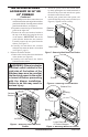
Figure 20 - Mounting Blower to Firebox
Green
Ground
Wire
Screws
Blower
Lower Rear
Wall of Firebox
Top Mounting
Tab
Exhaust Port
Screw
INSTALLING BLOWER
ACCESSORY IN 32”
FIREPLACE SYSTEMS
NOTICE: Shut off gas supply and
disconnect heater from gas sup-
ply. Contact a qualied service
person to do this.
NOTICE: Not all 24" vent free gas
logs can be installed in a 32" re-
box with a blower. Please refer
to your gas log owner’s manual
for log sizing requirements.
Note: Appearance of rebox or burner system may
vary depending on model.
1. Remove replace screen per the instructions
in operation manual supplied with replace.
2. If logs are installed, carefully remove the logs
and set aside, noting the properly mounted
location of each.
3. Remove screws that attach log base assembly
to replace. Carefully lift up log base assem-
bly and remove from replace, taking care to
pull exible gas line through the access holes
(see Figure 19).
CAUTION: Do not pick up log
base assembly by burners. This
could damage burners. Only
handle base by grates.
Figure 19 - Removing Log Base from
Fireplace
Screws
Log Base
Flexible
Gas Line
19. Using speed control knob, turn blower on and
check for operation.
20. All remaining parts from blower kit may be
discarded.
OPERATING THE BLOWER
Light your gas appliance with the blower off. After
about 15 minutes, turn the blower on to deliver
heated air at the top louvers. The blower features
a variable control which allows you to select the
speed you desire.
4. Attach the power cord to the blower motor
by rmly pushing the two female terminals at
the end of the power cord onto the two spade
terminals on the blower motor.
5. Attach green ground wire from power cord
to blower housing using screw provided (see
Figure 18). Tighten screws securely.
6. Place the blower against lower rear wall of
rebox outer wrapper with the exhaust port
directed upward. Align the holes in top mount-
ing tabs of blower with holes in wall of wrap-
per (see Figure 20). Using 2 screws provided,
mount blower and tighten screws securely.
7.
Be certain that all wire terminals are securely at-
tached to terminals on blower motor and that the
screw retaining the green ground wire is tight.
8. Place control knob provided on plastic control
shaft of speed control.
INSTALLING BLOWER
ACCESSORY IN MODEL
SVFBC FREESTANDING
STOVE
Continued