
Installation Instructions


www.desatech.com
108319-01D
6
14. Replace and reattach rebox bottom using
4 screws removed in step 2 (see Figure 8,
page 4).
15.
If previously removed, carefully replace the re-
brick side panels and/or oor in the rebox (see
Figure 5, page 3 and Figures 6 and 7, page 4).
16. Install the log set heater according to the instal-
lation instructions supplied with the heater.
WARNING: A qualied ser-
vice person must install heater.
Follow all local codes.
Note: Discard the remaining hardware items.
OPERATING THE BLOWER
Light your gas appliance with the blower off. After
about 15 minutes, turn the blower on to deliver
heated air at the top louvers. The blower features
a variable control which allows you to select the
speed you desire.
Note: Periodically check the louvers of the rebox
and remove any dust, dirt or other obstructions.
INSTALLING BLOWER
ACCESSORY IN 36" OR
42" FIREBOX
Continued
INSTALLING BLOWER
ACCESSORY IN MODEL
SVFBC FREESTANDING
STOVE
NOTICE: Shut off gas heater
during the following blower
installation.
1. Remove top panel of stove by removing three
screws from under top lip on each side of stove
(see Figure 13).
2. Facing front of stove, carefully slide top panel
forward until it is completely removed from
stove (see Figure 13).
3. Disconnect power cord wires from blower
motor (if connected) (see Figure 14).
4. Disconnect green ground wire from blower
housing (if connected) by removing screw
holding wire terminal (see Figure 14).
5. Install one plastic bushing provided in blower
kit into the 1
1
/2" hole in the left rear of rebox
oor. Access hole through the rectangular
opening in the rear panel (see Figure 15).
6. Remove the two blower mounting brackets
from the rear panel by removing two screws
each (see Figure 16, page 7).
7. Attach the two mounting brackets to blower
housing using four screws provided in
blower kit (2 for each bracket) (see Figure
16, page 7). Tighten screws securely. Place
blower assembly temporarily on top of
rebox.
8. Working from the rear of the stove, place entire
power cord, including speed control housing,
in lower control compartment.
9. Route ends of 3-wire power cord up from the
lower control compartment through the plastic
bushing, then up to the upper cavity of stove
(see Figure 17, page 7).
10. Attach the terminal ends of the white and
black power cord wires to the terminals on the
blower motor (see Figure 14). Push rmly.
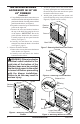
Figure 13 - Removing Stove Top Panel
Figure 14 - Removing Wires from Blower
Figure 15 - Installing Bushing
Screw
Green Ground Wire
White
Powercord
Wire
Black Powercord Wire
Bushing