
Installation Instructions


www.desatech.com
108319-01D
5
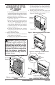
Figure 10 - Installing Plastic Bushing for
Power Cord
1
1
/2" Hole
Plastic
Bushing
Plastic
Hole Plug
Figure 11 - Attaching Speed Control to
Firebox
Speed Control
Control Shaft
Locknut
Control
Knob
V
ar
ia
bl
e
F
a
n
Sw
it
c
h
W
hi
t
e
W
hi
te
Bl
a
c
k
Gr
e
en
On
11
0
/
1
1
5
V
.
A
.
C
.
Bl
o
w
e
r
M
o
t
o
r
B
l
a
c
k
B
l
ac
k
Bl
a
ck
Of
f
Figure 12 - Location of Wiring Diagram Decal
Wiring Diagram Decal
12” in Front of Blower
Floor
Supports
1
1
/2"
Hole
INSTALLING BLOWER
ACCESSORY IN 36" OR
42" FIREBOX
Continued
5. Place the blower against the lower rear wall
of the rebox outer wrapper with the exhaust
port directed upward. Align the holes in top
mounting tabs of blower with holes in wall
of wrapper (see Figure 9, page 4). Using 2
screws provided, mount blower and tighten
screws securely.
6.
Be certain that all wire terminals are securely at-
tached to terminals on blower motor and that the
screw retaining the green ground wire is tight.
7. Locate the plastic hole plug installed in the
3/8" diameter opening in the lower right side
of the rebox front panel (see Figure 10).
Remove the plastic plug and discard.
8. Place speed control against inner wall of
front panel, pushing the plastic control shaft
forward through the opening.
9. While supporting speed control, secure control
shaft with lock nut by pushing and turning
lock nut with pliers clockwise until it is tight
against front panel. Place control knob pro-
vided on shaft (see Figure 11).
10.
Turn on power to duplex outlet if previously
turned off per the warning in column 1, page 4.
11. Plug in blower power cord.
a. If your firebox is installed as a free-
standing unit with an accessory mantel,
determine whether the power cord will exit
the left side or the right side of the rebox.
Install 1 plastic bushing provided into the
1
1
/
2
" hole in the oor support on the exit
side. Install the second plastic bushing
provided into the 1
1
/
2
" hole in the outer
casing through which the power cord will
exit (see Figures 10 and 12). Route power
cord through both plastic bushings and plug
the power cord into a wall receptacle near
the rebox.
b. If your rebox installation is recessed
and/or pre-wired, plug the power cord into
the duplex outlet provided. Refer to your
rebox owner’s manual for instructions on
wiring the duplex outlet.
12. Check to make sure that the power cord is
completely clear of the blower wheel and that
there are no other foreign objects in blower
wheel. Turn blower on and check for operation.
Turn blower off by turning knob fully counter-
clockwise before continuing.
CAUTION: Never touch the
blower wheel while in operation.
13. Peel off the backing paper and stick the sup-
plied wiring diagram decal on the rebox bot-
tom approximately 12" in front of the blower
(see Figure 12).