
Installation Instructions


www.desatech.com
108319-01D2
INSTALLING BLOWER
ACCESSORY IN A 32"
FIREBOX
Notice: If a log set is currently in-
stalled in the rebox, disconnect
log set from gas supply and remove
from rebox. Contact a qualied
service person to do this.
Notice: Not all 24" vent free gas
logs can be installed in a 32" re-
box with a blower. Please refer
to your gas log owner’s manual
for log sizing requirements.
Note: Appearance of rebox may vary slightly
depending on model.
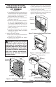
1. Remove the rebox bottom:
a. Remove the 4 screws that secure the bottom
of the rebox (see Figure 1).
b. Carefully raise and remove the firebox
bottom from the rebox.
WARNING: If there is a duplex
electrical outlet installed in the
right side of the bottom of the
replace base area, be sure that
the electrical power to the outlet is
turned off before proceeding with
blower installation. Failure to do
this may result in serious injury.
2. Attach the power cord to the blower motor
by rmly pushing the two female terminals at
the end of the power cord onto the two spade
terminals on the blower motor.
3. Attach green ground wire from power cord
to blower housing using screw provided (see
Figure 2). Tighten screws securely.
4. Place the blower against lower rear wall of
rebox wrapper with the exhaust port directed
upward. Align the holes in top mounting tabs
of blower with holes in wall of wrapper (see
Figure 2). Using 2 screws provided, mount
blower and tighten screws securely.
5.
Be certain that all wire terminals are securely at-
tached to terminals on blower motor and that the
screw retaining the green ground wire is tight.
6. Locate the plastic hole plug installed in the
3/8" diameter opening in the lower right
side of the rebox front panel (see Figure 2).
Remove the plastic plug and discard.
Figure 1 - Removing Screws from
Firebox Bottom
Screws
Figure 2 - Mounting Blower to Firebox
Screws
Blower
Lower
Rear Wall
of Firebox
Wrapper
Floor
Supports
Top
Mounting
Tab
Exhaust Port
Plastic Hole Plug
Screw
Note: Appearance of replace may vary by model.
Speed
Control
Lock
Nut
Control Knob
Control
Shaft
Figure 3 - Attaching Speed Control
7. Place speed control against inner wall of
front panel, pushing the plastic control shaft
forward through the opening (see Figure 3).
8. While supporting speed control, secure control
shaft with lock nut by pushing and turning
lock nut with pliers clockwise until it is tight
against front panel. Place control knob pro-
vided on shaft (see Figure 3).