
Installation Instructions


www.desatech.com
108319-01D
10
Figure 23 - Location of Wiring Diagram
Decal 3" from Blower
Wiring
Diagram
101584-05
120 Vac. 60 Hz. . 78 Amps
DESA, Bowling Green, KY
Variable
Fan Switch
WhiteWhite
Black
Green
On
110/115
V.A.C.
Blower
Motor
Black
Black
Black
Off
WARNING: Never attempt to service heater
while it is plugged in, operating or hot. Burns
and electrical shock could result. Only a qualied
service person should service or repair heater.
If any of the original wire as supplied with the appli-
ance must be replaced, it must be replaced with 105°C
wire or it’s equivalent.
WARNING: Label all wires prior to discon-
nection when servicing controls. Wiring errors
can cause improper and dangerous operation.
Verify proper operation after servicing.
16. Connect gas supply to replace per instruc-
tions in operating manual provided with
replace.
WARNING: A qualified
service person must connect
replace to gas supply. Follow
all local codes.
INSTALLING BLOWER
ACCESSORY IN 32" FIRE-
PLACE SYSTEMS
Continued
INSTALLING BLOWER
ACCESSORY IN
FREESTANDING STOVE
SERIES SDV, MSD, MSTD,
CDV OR CSDBN
IMPORTANT: Read all installa-
tion instructions before install-
ing blower.
NOTICE: Shut off gas supply and
disconnect heater from gas sup-
ply. Contact a qualied service
person to do this.
INSTALLING THE BLOWER
1. Remove 4 hex bolts securing rear cover to
back of stove body (see Figure 24).
2. Separate bottom cover from rear cover by loos-
ening the 8 mounting screws (see Figure 24).
3. Align the holes in the top mounting tabs of
blower with the holes in wall of rear cover
(see Figure 25, page 11). Using the 4 screws
provided, mount blower and tighten screws
securely.
4. Attach the power cord to the blower motor
by rmly pushing the two female terminals at
the end of the power cord onto the two spade
terminals on the blower motor.
5. Attach green ground wire from power cord
to blower housing using screw provided (see
Figure 25, page 11). Tighten screw securely.
6. Make sure all wire connections to terminals on
blower motor are securely attached and that the
screw retaining the green ground wire is tight.
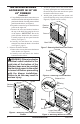
Figure 24 - Removing/Installing Rear
Cover
Screw Rear Cover
(Note: Stove Body
May Vary by Model)
OPERATING THE BLOWER
Light your gas appliance with the blower off. After
about 15 minutes, turn the blower on to deliver
heated air at the top louvers. The blower features
a variable control which allows you to select the
speed you desire. Note: Periodically check the
louvers of the rebox and remove any dust, dirt
or other obstructions.