
Instruction Manual

WAFER-CV-D25502/N26002 3.5" Motherboard
Page 34
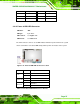
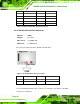
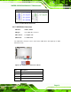
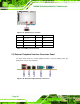
Figure 3-21: USB Connector Location
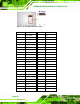
Pin Description Pin Description
1 USB_VCC 2 GND
3 DATA- 4 DATA+
5 DATA+ 6 DATA-
7 GND 8 USB_VCC
Table 3-23: USB Connector Pinouts
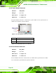
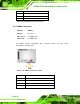
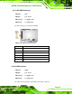
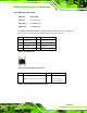
3.3 External Peripheral Interface Connector Panel
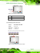
The figure below shows the external peripheral interface connector (EPIC) panel. The
EPIC panel consists of the following:
Figure 3-22: External Peripheral Interface Connector