
Instruction Manual

WAFER-CV-D25502/N26002 3.5" Motherboard
Page 20
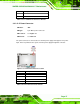
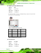
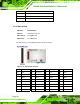
3.2.5 Digital Input/Output (DIO) Connector
CN Label: DIO1
CN Type:
10-pin header
CN Location:
See 6Figure 3-6
CN Pinouts:
See 6Table 3-7
The digital input/output connector is managed through a Super I/O chip. The DIO
connector pins are user programmable.
Figure 3-6: Digital I/O Connector Location
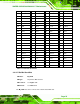
Pin Description Pin Description
1 GND 2 VCC
3 Output 3 4 Output 2
5 Output 1 6 Output 0
7 Input 3 8 Input 2
9 Input 1 10 Input 0
Table 3-7: Digital I/O Connector Pinouts
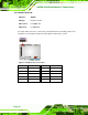
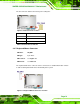
3.2.6 Fan Connector
CN Label: CPU_FAN1
CN Type:
3-pin wafer
CN Location:
See 6Figure 3-7
CN Pinouts:
See 6Table 3-8