
Manual


WAFER-CV-D25501/N26001 3.5" Motherboard
Page 48
individual power supply unit, the cooling fan of a power supply can also help generate
airflow through the board surface.
NOTE:
IEI has a wide range of chassis available. Please contact your
WAFER-CV-D25501/N26001 vendor, reseller or an IEI sales
representative at
3sales@iei.com.tw or visit the IEI website
(
3http://www.ieiworld.com.tw) to find out more about the available
chassis.
4.5.2 Motherboard Installation
To install the WAFER-CV-D25501/N26001 motherboard into the chassis please refer to
the reference material that came with the chassis.
4.6 Internal Peripheral Device Connections
This section outlines the installation of peripheral devices to the on-board connectors.
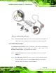
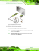
4.6.1 Audio Kit Installation
The Audio Kit that came with the WAFER-CV-D25501/N26001 connects to the 10-pin
audio connector on the WAFER-CV-D25501/N26001. The audio kit consists of three
audio jacks. One audio jack, Mic In, connects to a microphone. The remaining two audio
jacks, Line-In and Line-Out, connect to two speakers. To install the audio kit, please refer
to the steps below:
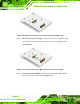
Step 1: Locate the audio connector. The location of the 10-pin audio connector is
shown in Chapter 3.
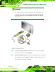
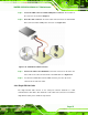
Step 2: Align pin 1. Align pin 1 on the on-board connector with pin 1 on the audio kit
connector. Pin 1 on the audio kit connector is indicated with a white dot. See
Figure 4-7.