
Manual


WAFER-CV-D25501/N26001 3.5" Motherboard
Page 37
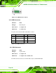
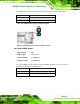
Pin Description Pin Description
1 RED 2 GREEN
3 BLUE 4 NC
5 GND 6 GND
7 GND 8 GND
9 VGAVCC 10 GND
11 NC 12 DDCDAT
13 HSYNC 14 VSYNC
15 DDCCLK
Table 3-26: VGA Connector Pinouts
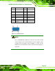
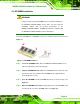
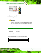
Figure 3-24: VGA Connector
NOTE:
Due to Intel® GMA driver limitation, the monitor connected to the VGA
connector may become extended desktop or not have signal to it after
restarting from the graphics driver installation. To work out this
limitation, press the Ctrl+Alt+F1 hotkey to switch the primary display to
CRT mode.